I'm replacing a 60 year old PT-105 Power transformer on a '58 Ampeg Jet and have discovered that the V1-V4 tube heaters are not wired per the schematic.
Instead of the 2 legs of the 6.3v windings running down the opposite sides of the heaters in parallel with the center tap grounded as shown, one leg of the winding (green) runs to one side of the heaters and the other leg (green) goes to ground. The other side of the heaters also go to ground. The Gr/white lead (CT) is capped. Seems to me like this is putting voltage on the chassis. Seems like this works with a 2 wire cord but would be incompatible with a 3 wire power cord, likely tripping any GFCI it's plugged in to.
Am I wrong in thinking that the thing to do here is to rewire these heaters in line with the schematic to accommodate the 3 wire cord?
Attachments
It is not really putting voltage on the chassis.
One side of the heaters is at 0V and the other is at 6.3V AC.
With the heater winding centre tap to ground instead, you effectively have each side of the heaters at 3.15V AC but with opposite phase. When you then twist those wires together, the electomagnetic fields from the AC current in those wires cancel each other and so that is the quieter option.
If you do not have a hum issue then don't bother changing it. If you do have a hum issue it MAY be quieter if you rewire the heaters as parallel twisted wires with a centre tap (real or peudo CT) to ground.
Cheers,
Ian
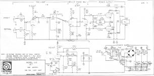
Mine is a J12B as shown in the schematic I attached. The schematic you posted is for a newer Jet using 12AX7's/7591's & a SS rectifier. The J12B I have uses 6SL7's/6V6's & a 5Y3 rectifier. SN puts it in 1958.
Heaters one side grounded was VERY common in radios, and in early guitar amplifiers.
As normally done (heater pin bend and soldered to chassis) it puts *current* in the chassis.
In higher-gain amplifiers the heater current and the unbalanced heater fields cause some hum. Fashion changed to running two wires and grounding a CT.
That amp is not high gain. It may be "fine" to repair it exactly the way it was built.
- Status
- Not open for further replies.