Gavin
If you check the link I placed in my post above there is credible advise on building this project. I followed it and obtained a good workable unit. If you follow the article thru you will see that others have also built the same circuit and some have modified it to suit their personal tastes. I built the power supply as stated and there is NO ringing. I checked the supply and it looked clean on the scope. My modifications to the supply were the addition of VR tubes in the power supply and DC to the heaters. Those that listened to my line stage seemed to prefer the VR addition to the standard supply. I do believe that the 50mfd caps in the supply might tax the little 6X4 somewhat. Personally, I would rather use a tube rectifier than SS diodes (1N4000 family) as I feel they lack the warmness found with tube power supplies.
I still have the line stage but in piece form as I used its chassis and power supply for my 12B4 line stage project. I did find the Tung-Sol tubes to be a bit microphonic but had very good results with the Philips black plate tube. I also played with various plate voltages and currents and found their setting to be the most pleasing to my old ears. Frank it correct in thinking the 5Y3 might be a bit overkill, but then maybe you have a shoe box full of them.
Build it😀
burnedfingers said:Gavin
If you check the link I placed in my post above there is credible advise on building this project. I followed it and obtained a good workable unit. If you follow the article thru you will see that others have also built the same circuit and some have modified it to suit their personal tastes. I built the power supply as stated and there is NO ringing. I checked the supply and it looked clean on the scope. My modifications to the supply were the addition of VR tubes in the power supply and DC to the heaters. Those that listened to my line stage seemed to prefer the VR addition to the standard supply. I do believe that the 50mfd caps in the supply might tax the little 6X4 somewhat. Personally, I would rather use a tube rectifier than SS diodes (1N4000 family) as I feel they lack the warmness found with tube power supplies.
I still have the line stage but in piece form as I used its chassis and power supply for my 12B4 line stage project. I did find the Tung-Sol tubes to be a bit microphonic but had very good results with the Philips black plate tube. I also played with various plate voltages and currents and found their setting to be the most pleasing to my old ears. Frank it correct in thinking the 5Y3 might be a bit overkill, but then maybe you have a shoe box full of them.
Build it😀
Hi Fingers. Did you use regulated DC supply or a simple filtered one? I chose the 20 H chokes because, since I use steel top plates I prefer for all of the transformers to be above the chassis to give me a little EMI shielding. The chokes that were used in the project that you pointed out are not very nice looking so I chose to go with the 193 series chokes. I really didn't think it would make a huge difference. My chassis is only 12 x 12 but I think that I can squeeze a couple of OD2s on it to do the shunt regulator (one for each channel). I have the caps and SS bridge to do DC heating if I use a simple filtered supply. I also have some Mill's 12 watt 1 ohm and 2 ohm resistors and a couple of Allen Bradley 5 watt 100 ohm ww pots to make it adjustable. I have all of the stuff but I'm unsure of which direction to go at this point. For every idea you have you are going to be given a dozen reasons it willl not work as well as you hoped. Yes I do have several 5Y3Gs as well as 5AR4s. I was just going to build a simple preamp to go with my amplifier. Now I'm not sure.
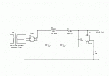
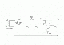
Keep in mind when you look at this supply that I have no experience with tube diodes. I think it is right but don't take this design and go build it until it is verified by some of our more learned members. I am showing only the supply for one channel. It will be doubled after the rectifier if I use the design. Please give me any suggestions that pop into your collective heads. The 10K resistor may not work where I have it placed nor at that value. Here is my first attemp at a shunt regulated supply:
Attachments
Hi,
Gavin,
Unfortunately it doesn't work as shown.
If you want to regulate 300VDC using glowdischarge tubes you need to stack a number of them to arrive at your target voltage, you'll need some spare volts to ignite them and set the current you want to run through them too.
In this case, assuming you'd want 300V you need to stack 2* 150V glowdischarge tubes and set them at around the midpoint of their current range.
That's like two OA2s set at 17mA current for an average deviation from target voltage of 6VDC at a max. current draw of 30mA.
Since you have a Class A circuit you only need to worry about having the tubes firing and staying within the max. permissible current.
After that the two tubes can be shunted with a 0.100µF film cap of say, 400-450VDC if deemed necessary.
Keep in mind you can't add any more capacitance after your shunt reg or it will definetely oscillate.
Maximum starting voltage for the OA2 is 185V each together with a maximum initial current draw of 75mA.
These are maximum ratings for the OA2 so you'd better settle for a little less.
Remember you're regulating a circuit operating in Class A, so current draw is pretty much constant.
Drawing about 20mA from the reg. isn't a big deal as you're not likely to go past 30mA under normal operating conditions anyway.
Hope this helps,😉
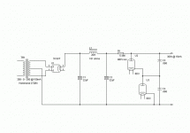
Hi Frank. I think this is close to what you are talking about. I used .068 caps across the 0D3s because the data sheet says the .1 is the limit. So I gave it some margin. I also lowered the 6.49K dropping resistor to 5.49K to give it a few extra volts.
Attachments
Hi,
A single .068µF capacitor across both tubes would be more appropriate although it's not possible to tell how effective it is without looking at the PSU on a o-scope.
Caps in series see their total value divided by the number of caps: Ctot = C/n
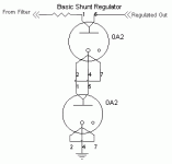
I have no idea about the wiring diagram of the OD3 but I assume it's similar to the one of the OA3 (both are 150V VRs if I'm not mistaken), to make the PS failsafe in case of tube failure use this wiring diagram:
It actually opens the B+ line to the 5687 circuit when one of the VR tubes is pulled or fails.
Cheers, 😉
Attachments
Hi Frank. The 0A2 will take up less room so I will use those. Octals are easier to work with but in this case they are too big. Would you explain to me what controls the current through the regulator tubes? I have the dropping resistor set to so the supply will deliver 324 volts into a 20K load @ about 15mA without the regulator string. The load is in parallel with the regulator string so how does that effect the current through the load? I'm a little confused to say the least. Anyway here is the latest. I will connect the 0A2s as you suggested. I had read about that while searching through datasheets. Thanks.
Attachments
Gavin
There was a thread a months back that had a link to some very interesting technical information about setting up the VR tubes correctly. I will continue looking for it and will post it if I find it. If someone else remembers what the heck I'm refering to maybe they will jump in and post it. I used to have it saved but when the hard drive gave up the info was lost.
Burnedfingers
After reading the info here:
http://www.tpub.com/content/neets/14178/css/14178_148.htm
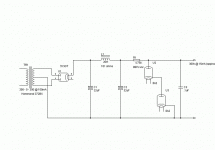
on VR tubes and the calculations needed to design a shunt regulated power supply I have come up with the design below. Anyone care to double check my math? I had to make a compromise on the dropping resistor as I couldn't find a 2.8K resistor. Imagine that.😉 I also had to up the VA rating on the transformer to account for the extra current. It shouldn't be a problem though.
Attachments
Hi,
The circuit looks fine to me...doing the maths on this kind of stuff is notoriously hard though.
Time to build I'd say.🙂
Cheers,😉
The circuit looks fine to me...doing the maths on this kind of stuff is notoriously hard though.
Time to build I'd say.🙂
Cheers,😉
I couldn't find a 2.8K
I've just finished writing a proggie that helps here.
It finds best matches for any required value between 0.5ohm and 20Mohm for E24 (1%) series and 47ohm and 1Mohm for E96(1% & 0.1%) series (default settings).
click here to get ResCalc
ResCalc tells me there are 5 ways to get 2k8 using cheap E24 series resistors. Or just a single using E96.
And you get the colour bands too.
It might help? .. I dunno... fun to write though.
Scary .exe files
Many people will be wary about running an unknown (no disrespect intended) exe file on their PC's.
To that end, I just ran it in a virtual PC, and it caused no destruction 😉
I cannot virus check it at present, but it's up to each person who is forced to work with PC's to check every file they receive.
Thanks for posting.
I note the authors 😎
Hello Dhaen,
Oops, yes, I'm sorry.
I should have pointed out that the proggie was virus checked (clean) before posting to my website.
It's deliberately a .zip file so it can be virus checked after download and before running.
I totally agree, you have to be careful when downloading software.
ResCalc doesn't alter any system settings, nor does it write to the Windows registry ... I hate that kind of thing.
Give it a go, I've used it in the RIAA stage I'm putting together.
Any bugs, let me know.
Actually, as you can run a virtual PC (as can I) check it out in detail just to assure I'm not posting someting nasty. ... that ain't me 🙂
ResCalc is quite good really at what it does.
- Status
- Not open for further replies.
- Home
- Amplifiers
- Tubes / Valves
- 5687 Preamp as I plan to build it.
