Hi All,
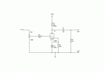
Here is the 5687 preamp as I plan to build it. Simple and to the point. I'm going to brave the hazards of AC filament voltage on this project. Hopefully my layout and grounding scheme will be up to the task. I decided on the 5y3 because of the minimal current demand. Any suggestions are welcome.
Here is the 5687 preamp as I plan to build it. Simple and to the point. I'm going to brave the hazards of AC filament voltage on this project. Hopefully my layout and grounding scheme will be up to the task. I decided on the 5y3 because of the minimal current demand. Any suggestions are welcome.
Attachments
Gavin
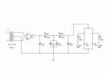
When I built my 5687 I used a VR regulated supply and it sounded better with it than without. I also used 30H chokes in the power supply and DC on the filaments.
It is a nice sounding line stage but somewhat pale when up against a 12B4 line stage.
Joe
When I built my 5687 I used a VR regulated supply and it sounded better with it than without. I also used 30H chokes in the power supply and DC on the filaments.
It is a nice sounding line stage but somewhat pale when up against a 12B4 line stage.
Joe
Hey Fingers. Did you use a tube regulated supply or a SS regulated supply? Can you post a diagram? I'm actually considering using a shunt regulated supply with OD3s. Aren't you proud Frank and SY? 😀 😀 😀 😀
Gee, seems like a waste of a 5Y3 to me. 😛 (20H chokes too, but I digress.) A 6X5 would work, you might be able to find a stylish model, Idunno...
Properly handled, you'll find AC heaters work very nice indeed.
Tim
Properly handled, you'll find AC heaters work very nice indeed.
Tim
burnedfingers said:Gavin
When I built my 5687 I used a VR regulated supply and it sounded better with it than without. I also used 30H chokes in the power supply and DC on the filaments.
It is a nice sounding line stage but somewhat pale when up against a 12B4 line stage.
Joe
I suppose I will have to avoid listening to 12B4A linestages.
😉
Quote: Properly handled, you'll find AC heaters work very nice indeed.
Gee, I suppose a VR regulated supply and rectifier tube would be a waste also.
Gee, I suppose a VR regulated supply and rectifier tube would be a waste also.
Well, as a coincidence the two amps I use (Frankenhouse and Hept'AU7) both have rectifiers, but they just happen to have more power and sound most similar than anything else I have. I'm a lazy builder 🙄
You can reg if you want but it won't affect anything as far as I'm concerned.
Tim
You can reg if you want but it won't affect anything as far as I'm concerned.
Tim
I see nothing wrong with the 12B4. I haven't done anything besides a really abusive circuit 😀 but it looks great. Maybe I'll build a PPP or PSE amp some day with 'em...
Tim
Tim
I was curious about your design, so I broke out the sim tools. 🙂
Chose 29 Ma as the bias current. Got that from a tube cad simulation of the circuit. The circuit sim looked good.
I ran a simulation on Duncan amp tools.
It looked to me that the supply had some ringing.
You may want to re-visit your design.
This may or may not be an issue in the real circuit.
Just thought you would want to know.
Cheers;
Doug
Sch3mat1c said:Gee, seems like a waste of a 5Y3 to me. 😛 (20H chokes too, but I digress.) A 6X5 would work, you might be able to find a stylish model, Idunno...
Properly handled, you'll find AC heaters work very nice indeed.
Tim
Would you care to elaborate? Why would the 5Y3 and the chokes be a waste? If you have an opinion spit it out.
DougL said:I was curious about your design, so I broke out the sim tools. 🙂
Chose 29 Ma as the bias current. Got that from a tube cad simulation of the circuit. The circuit sim looked good.
I ran a simulation on Duncan amp tools.
It looked to me that the supply had some ringing.
You may want to re-visit your design.
This may or may not be an issue in the real circuit.
Just thought you would want to know.
Cheers;
Doug
Hi doug. I wasn't aware that you could spot ringing using Duncan's amp tools. I have mine designed to run at 15mA. Maybe that would make a difference. I don't own a scope so I have never looked at ringing. Maybe bypassing the 32uF caps with film caps would help. When you say ringing I'm assuming you are talking about ringing in the supply?
If I understood your power supply schematic, Both tubes are using the same power supply. I got 14.3 Ma Using Tube Cad and doubled it. That puts us very close, 29 vs 30 ma.I have mine designed to run at 15mA
I wasn't aware that you could spot ringing using Duncan's amp tools.
My understanding is a couple of things will point to ringing.
The first is to watch the PS circuit power up. The Voltage on the cap connected to the Plate resistors (last Cap) should have a smooth rise from 0 to 350V if powered up without soft start.
Another way is to use the step function. after 2 minutes, I stepped the current load from 29 to 35 ma. Zooming in on the change, I could see ringing as the voltage transitioned.
Regards;
Doug
DougL said:
If I understood your power supply schematic, Both tubes are using the same power supply. I got 14.3 Ma Using Tube Cad and doubled it. That puts us very close, 29 vs 30 ma.
My understanding is a couple of things will point to ringing.
The first is to watch the PS circuit power up. The Voltage on the cap connected to the Plate resistors (last Cap) should have a smooth rise from 0 to 350V if powered up without soft start.
Another way is to use the step function. after 2 minutes, I stepped the current load from 29 to 35 ma. Zooming in on the change, I could see ringing as the voltage transitioned.
Regards;
Doug
Sorry. I thought you meant 30mA per channel. Not thinking. Do you have a recommendation for reducing the ringing? Bypass the electrolytics with film caps?
G said:
Would you care to elaborate? Why would the 5Y3 and the chokes be a waste? If you have an opinion spit it out.
You're using what, 20mA? ...30? Not much oomph for a 5Y3. So much filtering isn't necessary unless you have a really crappy design, which you don't. I'd throw in 10-40uF at the rect. (whatever's recommended), 5-10H and 100uF. Plenty low hum.
Tim
Gavin
Check out http://diyparadise.com/simplepreamp.html
there is use of chokes in the power supply as well as a 6X4 rectifier tube in the power supply. In my opinion there is nothing wrong with using a 5Y3 in place of a 6X4 as its a matter of choice.
I still believe that VR tubes lend a simple smoothness to the sound. Just my .02 for what its worth.
Joe
Hi,
Regarding ringing in PSUs containing filter chokes:
It's my experience that if you choose the cap values to go from low to higher values you more often than not don't have the LC part ringing unless you really use crappy caps and awkward chokes.*
*Read unfortunate combinations of ESR, DCR, whatever triggers it.
If you have several identical chokes it's also my experience that you're often better served using each one to split the PSU so each channel sees its own PS starting from right behind the choke instead of using both in a CLCLC series filter that would than be common to both channels.
I have no idea whether this correlates with whatever sims spit out. If it doesn't then I may have to either revise my opinion or look for a different reason as to why this yields such fine sonic results.
Something that's often forgotten is that rectifier tubes, just like other tubes work best at certain voltages and currents.
Use the datasheets wisely, they often contain heaps of engineering expertise not easily found elsewhere.
As a last point, I agree with Tim in that the 5Y3 is overkill here currentwise.
It's much easier to lay out heaterwiring and avoiding induced hum when there's fewer current circulating around.
This can be tricky in a circuit as sensitive as a preamp....
For those of you wanting to experiment with this; try building highly sensitive circuits such as MC headamps and watch me use heaterwire not much thicker than a hair to rid the circuit of its last ounce of PS noise.
Remember, a circuit diagram is only a blueprint...not a house.
Cheers, 😉
Quote:Remember, a circuit diagram is only a blueprint...not a house.
The true words of a master.
The true words of a master.
To Obi- Wan you listen. 🙂
My advice is to play with the Dunkin Amp tools using Frank's guidelines and post your revised PS.
Doug
My advice is to play with the Dunkin Amp tools using Frank's guidelines and post your revised PS.
Doug
Hmmm....thin heater wire will increase resistance, cooling cathodes and making possible problems for the insulation. You can get the wires closer so they cancel more field but that shouldn't make much difference unless you purposely loop signal wires around them like a pickup coil. Not like I know anything about milivolt signals.
Tim
Tim
- Status
- Not open for further replies.
- Home
- Amplifiers
- Tubes / Valves
- 5687 Preamp as I plan to build it.