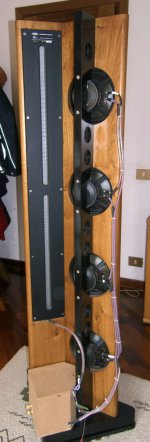
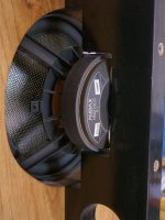
There's been a few different ways that the Orion's 8" was mounted. The 2 main ones --
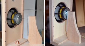
1. a kind of metal cup & brace to hold the magnet to the back post. I believe the driver had to be glued to the cup. (first 2 pics below)
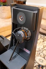
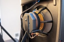
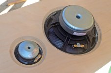
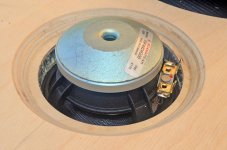
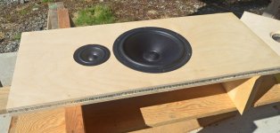
2. a threaded metal rod replaces the bolt that holds the copper phase cap of the W22EX00, and this rod is used to clamp the driver between the phase cap and the back post. This is what I did. (last 2 pics below) Total PITA to line it up just so, but it got done in the end.
1. a kind of metal cup & brace to hold the magnet to the back post. I believe the driver had to be glued to the cup. (first 2 pics below)
2. a threaded metal rod replaces the bolt that holds the copper phase cap of the W22EX00, and this rod is used to clamp the driver between the phase cap and the back post. This is what I did. (last 2 pics below) Total PITA to line it up just so, but it got done in the end.
Attachments
BTW, the Scanspeak 22W8534 8" driver I'm using in the 521 baffle has a vent hole like the Seas W22EX00 but no phase cap. It's John K's choice of lower mid for his NaO Note II RS. I had a pair originally meant for JK's design but that never got built, so I pressed them into service here. On spec, very similar to the Seas U22REX/P-SL 8" in the LX521. (Ditto the Scanspeak 10F driver -- from JK's design, not LX521). Actually I'm only using the baffle shape from the 521, and that's an approximation.
just to give you an idea.Another problem is how to fix the magnet to the pole/rest - I use velcro strip which isn't as rigid as I'd like it to be. But I don't want to use epoxy glue either... Extra challenge would come if the magnet had a vent in the middle like many SB Acoustics woofers.
this was my first dipole, the woofers were blocked by the magnet, a stainless steel screw passing up to the other side of the magnet and here a washer takes the frame and the magnet and the nut tightens.
the depth of the opening for the magnet must be precise otherwise the washer does not bite the magnet.
I hope I explained myself.
Attachments
Scott, your comments point back to the Linkwitz Orion approach to the 8" driver mounting. In my 521 baffle the 8" is the primary source of large vibration, so mounting it via magnet to a back post and detaching it from the baffle would have the biggest impact. Worth thinking about, tho aesthetically challenging and probably detrimental to the dipole effect.
Think about this in the "inverse":
Decreasing mass (both as a means of reducing movement along with *sinking some of that energy) with decreasing force.
1. rigid + massive = baffle (with it's own support) for the 8".
2. rigid + much less massive = midrange coupling **ring (with its own support), decoupled from the baffle (..soft silicone caulk to bridge the gap between baffle and "ring").
3. rigid + little mass = tweeter coupling **ring (with its own support) decoupled from the baffle (..soft silicone caulk to bridge the gap between baffle and "ring").
*If you don't do this you often have more energy left in the frame causing problems with the driver (driver dependent), typically creating higher non-linear distortion as a result. (..I don't like the Klippel method of "clamping" the driver free-air and then doing broad-band near-field tests for non-linear distortion: you often end-up with more distortion measured than what can be achieved with a more typical mount on baffle.)
**I say "ring" here, but the shape of a ring is probably the least ideal, maybe a rectangle?
BTW, mounting to wood is not rigid: comparatively speaking it's a soft surface vs a hard aluminum alloy (or better: steel). Cement can also be pretty good, but usually requires threaded metal inserts.
Last edited:
With its own support???Think about this in the "inverse":
Decreasing mass (both as a means of reducing movement along with *sinking some of that energy) with decreasing force.
1. rigid + massive = baffle (with it's own support) for the 8".
Those words are just confusing. There's only one baffle board, so how do you propose rigid & less massive when you want "more massive" for the 8"? Adding viscosity to driver mounting was tried and abandoned by commercial spkr makers a long time ago for many good reasons: Are you proposing a return to this? 1980s KEF/B&W O-ring grommets around mounting bolts and such?2. rigid + much less massive = midrange coupling **ring (with its own support), decoupled from the baffle (..soft silicone caulk to bridge the gap between baffle and "ring").
Ditto. confusing.3. rigid + little mass = tweeter coupling **ring (with its own support) decoupled from the baffle (..soft silicone caulk to bridge the gap between baffle and "ring").
You'll have to show example pics.
My preference is for lower mass & higher stiffness/damping in the baffle. Hence the aerolam/BB laminate -- it's lighter and stiffer & better damped than similarly thick BB alone. Keeping the big vibrations of the 8" from getting into the baffle strikes me as far more logical than decoupling the 4" & tweeter, which don't make enough vibration, imo, to cause as much trouble in the baffle anyway.
True enough, but we all accept compromises. BB that's well supported & braced is good enough for me.BTW, mounting to wood is not rigid: comparatively speaking it's a soft surface vs a hard aluminum alloy (or better: steel). Cement can also be pretty good, but usually requires threaded metal inserts.
True enough, but we all accept compromises. BB that's well supported & braced is good enough for me.
..but it won't get you the same subjective result you mentioned. 😉
-as to the rest, I'd do a 3-d model - but I don't have that kind of time. 😱
And your approach will? The approach which I notice you didn't clarify any further...but it won't get you the same subjective result you mentioned. 😉
I only cited the info re aluminum baffle because it demonstrates that there is a weakness in the 521 baffle design. For me, an 18mm-thick aircraft grade aluminum baffle is out of the question. If that's required to get the most from the Linkwitz design, then it's not such a great design, we can devise a smarter better design that doesn't require such a brute approach & expense.
I DIY onward with available resources. Lots of routering on the new laminate baffle today, but too wiped to post anything. Later.
..can you devise smarter and better than the thick aluminum baffle and get the same sort of effect?
Is it more expensive than the aerolam panel? (..I'm guessing something like SL's solution with 3/4" aluminum is around $500 - for both panels (L&R) though not the support-stand, and not including machining.) Really though, does it have to be aluminum? Steel plate would be about $275 and that's for the same thickness - which isn't required; 1/2" would probably be less than $175 and about 2x as heavy as the 3/4" Aluminum. Oh, and you wouldn't have a resonance due to a "tunnel".
Is it more expensive than the aerolam panel? (..I'm guessing something like SL's solution with 3/4" aluminum is around $500 - for both panels (L&R) though not the support-stand, and not including machining.) Really though, does it have to be aluminum? Steel plate would be about $275 and that's for the same thickness - which isn't required; 1/2" would probably be less than $175 and about 2x as heavy as the 3/4" Aluminum. Oh, and you wouldn't have a resonance due to a "tunnel".
Last edited:
My inclination would be to explore no-baffle designs rather than CNC cut 18mm t6061 aluminum 521 baffles. I can't see that being much less than a grand for a pair
The simple 2-bolt BB plates I made for the 12" driver in my Aino-G copy would work well to join drivers in a vertical array. See pics posted in previous posts. The driver frames would be integral to the rigidity & strength of this setup -- ditto the bolts & connection to the plates. The drivers in my collection would all fare well; the quality brands make very strong frames these days.
Between an 8" driver and a 4" driver, the connecting piece would probably be a maximum of 5x2". At that size, the stiffness & rigidity of BB is super high. It's such a small size that a cheap small 3/8" or 1/2" thick piece of aluminum would also work well. The rear radiation would be about as open as it could be. A back post of hardwood, steel or aluminum would probably be needed for additional support at the top, but all this is easily made in a DIY workshop at modest cost & effort. Just as important, it allows relatively easy, quick changes to experiment with different driver configs.
Fwiw, I bought the 4x10' sheet of aerolam as surplus from an aircraft maintenance company for CA$100 a few years ago, out of speculative interest. It's probably 5-10x that new. Maybe more -- I'd never buy it new or pay full price. Call me cheap but I prefer to think of it as eco-enlightened scavenging. �� (One of my buddies here grew up around a auto junkyard his father ran. Now, there's one amazingly creative DIYer!)
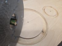
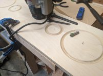
First a V-groove circle 7.5mm deep was cut into the back of the 9mm BB side for each driver. Then a flat trough circle 7.5mm deep, right up to the outer edge of the V-groove. On the front sides, rebates for the drivers were cut. Finally, the circle holes were cut for each driver.
All this took more time & effort than expected, partly because of the need to protect against cuts from aluminum shards and prevent inhalation of fiberglass bits. It's really too bad the skins of the aerolam are not also aluminum!
The drivers fit fairly well in their rebated holes, and the bigger chamfers allow lots of breathing room on the backside for both drivers.
The whole panel is super damped, and still feels very rigid... but the rigidity is slightly reduced compared to before the holes, judging by a manual deflection test. I'm now having doubts whether enough rigidity can be retained after reducing the panel to the 521 baffle shape. All of the 521 baffles I created have flex in the area between the mid drivers where the panel is narrowest.
Time to pause and reflect.
It just might not be possible to get the kind of rigidity I think is ideal in an 18mm 521 baffle without resorting to some kind of solid metal panel. 🙄
Attachments
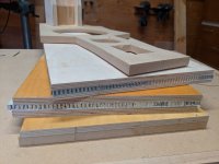
For the record, here's a pic showing the 4 boards I made (or planned to make) 521 baffles from. The first is probably subpar, being just 3/4" MDF, but the rest are all stronger & stiffer than the original, being both CLD & thicker. The most practical 25mm thick version (2nd from top) was still deemed too flexible. I will not be finishing my 521 build without serious modifications for baffle support.
Attachments
Mike, please can you measure just the woofers' response without any eq and xo, 180¤ polars sometime? How high do you estimate dipole pattern goes in freq? Cavity resonances should be well above lowpass anyway, and I suppose dipole peak too.[/url]
But what about harmonics? With such large excursions, there'll be plenty of harmonic distortion.
But what about harmonics? With such large excursions, there'll be plenty of harmonic distortion.
Measurements will tell that too. Multiway is needed for dipoles to control radiation pattern and distortion.
Distortion is the challenge in low end of passband and pattern in upper end. Typically there is 2-3 octaves of "nice" passband for each dipole driver. With a 4-way only low bass and high treble are compromized!
- Home
- Loudspeakers
- Multi-Way
- 521 & other open baffle experiments