Hello,
Anyone can suggest a 50W or greater stereo amplifier based on a single chip?
Simplicity is my goal as I am going to bring the sound to my taste using an input equilizer.
I think class-D would do as well...
I wish to avoid symmetric PSU too.
Anyone can suggest a 50W or greater stereo amplifier based on a single chip?
Simplicity is my goal as I am going to bring the sound to my taste using an input equilizer.
I think class-D would do as well...
I wish to avoid symmetric PSU too.
stereo chip i can not recall.
TDA1562 will do close to 50 watt from a single 15 volt rail into 4 ohms.
but it is not stereo, and not quite simple to build.
(before someone posts back telling it won't do more than X watts, the chip is class H, and BTL. from the 15 volt single supply it makes +- 30 volts.)
I would suggest TDA7294 point to point, it is well documented on these forums.
2 of them will give You stereo.
A split rail supply is needed, but that should be no problem.
Others chips i can think of have 2 channels, run on single supply, but will not do more than 8 watt or so into 8 ohm load.
Build a 2 x LM3886 amp.
Simple and very well documented.
Very popular so tons of hardware available such as transformers, PCB, heatsinks, chassis, etc.
Will easily do 50W per channel.
Lots of homemade ones pictures in a gallery here, so you can get some very clever construction ideas.
And so simple that it can even be built without a PCB, go figure.
Hi, just to mention, what about the dual 3886 chip? ; LM4780.
but, it´s symetric PS!
And there´s a p2p version too.
but, it´s symetric PS!
And there´s a p2p version too.
Single chip won't do 50+50W unless its classD. With classD no problem at all and plenty of choices with asymmetric supply.
National's 3886 datasheet shows a single supply implementation. The nice thing about that schematic is that it shows the "optional" components that have been omitted from the dual supply schematic.
National's datasheet show that the 3886 can do 50W in both the dual supply and the single supply versions.
The dual chip version of the 3886 (is it the 4780?) can do similar.
BUT I do not recommend the dual chipamp. It is too difficult to get the heat out of it.
I recommend two 3886 on separate but closely spaced PCBs.
the Akitika GT-101 is a good example of what you're looking for, in a complete kit. You can check out the schematics in the assembly manual here:
http://akitika.com/documents/AssemblyManualGT101rev1p38.pdf
http://akitika.com/documents/AssemblyManualGT101rev1p38.pdf
.
Chiming in mainly because I'm looking at some data sheets, what could possbly be simpler than an LM4780? Ebay has them for $10. Here's TI's data sheet: http://www.ti.com/lit/gpn/lm4780
The LM4780 needs about +/- 32 volts to develop 50 watts (depending), meaning a 48 volt center tapped power transformer...if you can find one. Or else two 24 volt transformers. In my view the power transformer(s) should be rated at least 120 watts (VA), 150 watts preferred.
With two channels on one chip, each running at 50 watts, chip cooling might best be done with a computer CPU heat sink and fan. These fans usually run at 12VDC, with current draw in the milliamp range, so a resistor voltage divider could power the fan. Or of course if you wind up using 24 volt center tapped transformers for the power supply, there's your 12 volts also.
However, I'm going to vote with AndrewT. It's hard to see a necessity for cramming everything into one chip. The transformer(s) and filter capacitors are going to take up far more space than the amp circuit board, so using two chips might make things easier in just the purely mechanical terms of putting things together. Although, in fairness to both approaches, there are hardly any components except the chip anyway.
.
Last edited:
.
<< I wish to avoid symmetric PSU too. >>
By symmetric, you mean you want to avoid using a dual/split power supply? Please excuse my blunt manner, but no you don't.
Running a chip designed for a split power supply on a single supply is a textbook exercise in doing thing the hard way for no good reason. More components, more expense, more chances for error. Whereas bolting together a real power supply is practically trivial.
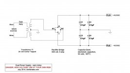
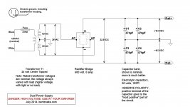
In testimony whereof I post the two schematics below, which I made up for another purpose, but they apply here as well.
The two are the same schematic--literally, since I edited one down to the other. The first is a bit bare bones, showing, I hope, the general simplicity of the thing. The second has some explanatory notes.
The voltages would have to be adjusted as needed, of course. And just to mention it, there are those who will disagree, but in my opinion buying toroid transformers for a power supply is a waste of money.
.
<< I wish to avoid symmetric PSU too. >>
By symmetric, you mean you want to avoid using a dual/split power supply? Please excuse my blunt manner, but no you don't.
Running a chip designed for a split power supply on a single supply is a textbook exercise in doing thing the hard way for no good reason. More components, more expense, more chances for error. Whereas bolting together a real power supply is practically trivial.
In testimony whereof I post the two schematics below, which I made up for another purpose, but they apply here as well.
The two are the same schematic--literally, since I edited one down to the other. The first is a bit bare bones, showing, I hope, the general simplicity of the thing. The second has some explanatory notes.
The voltages would have to be adjusted as needed, of course. And just to mention it, there are those who will disagree, but in my opinion buying toroid transformers for a power supply is a waste of money.
.
Attachments
Last edited:
National's 3886 datasheet shows a single supply implementation. The nice thing about that schematic is that it shows the "optional" components that have been omitted from the dual supply schematic.
National's datasheet show that the 3886 can do 50W in both the dual supply and the single supply versions.
The dual chip version of the 3886 (is it the 4780?) can do similar.
BUT I do not recommend the dual chipamp. It is too difficult to get the heat out of it.
I recommend two 3886 on separate but closely spaced PCBs.
I can see that in the dual supply version there is no huge 4700uf output cap, which is convenient!
the missing 4700uF capacitor is in the PSU.
A dual polarity supply has 2 smoothing caps. The amp output usually has none
A single polarity supply has one smoothing cap. The amplifier always has one to DC block the half supply voltage.
Both the dual polarity and the single polarity need two big caps.
If you study the two circuits you find they are actually the same. The cap just MOVES to a new APPARENT location.
But do remember that the pass band of both amplifier types are set by the input filters. NOT by the big caps in the PSU/output DC blocking.
the missing 4700uF capacitor is in the PSU.
A dual polarity supply has 2 smoothing caps. The amp output usually has none
A single polarity supply has one smoothing cap. The amplifier always has one to DC block the half supply voltage.
Both the dual polarity and the single polarity need two big caps.
If you study the two circuits you find they are actually the same. The cap just MOVES to a new APPARENT location.
But do remember that the pass band of both amplifier types are set by the input filters. NOT by the big caps in the PSU/output DC blocking.
Thanks Andrew.
I think i will go for the lm4780 running it (hopefully) cooler at 30-35W and use an input equilizer to bring the sound to my taste on a pair of small minimus-7. A higher wattage amplifier running at half volume, this is the scheme to be used.
Maybe a class-D amplifier could be used as well for more power saving, but I have not found any ultra simple design to 50W or so???
Agreeing with Andrew again
+1 for a voice of sanity.
I never could understand the rush to replace DC blocking caps with split rail PSU caps.
the missing 4700uF capacitor is in the PSU.
....
If you study the two circuits you find they are actually the same. The cap just MOVES to a new APPARENT location.
+1 for a voice of sanity.
I never could understand the rush to replace DC blocking caps with split rail PSU caps.
In bridged single supply designs you dont need output capacitor.
Id go for TDA7396 Its single supply and 45W peak output power.
And its simple as it can get+ sounds fine...
At 8 ohms the output power is only ~10W at ~0,03%THD
But at 15V DC thats quite amazing.
Id go for TDA7396 Its single supply and 45W peak output power.
And its simple as it can get+ sounds fine...
At 8 ohms the output power is only ~10W at ~0,03%THD
But at 15V DC thats quite amazing.
+1 for a voice of sanity.
I never could understand the rush to replace DC blocking caps with split rail PSU caps.
the bridged amp still needs at least 2 big capacitors.In bridged single supply designs you dont need output capacitor.
Id go for TDA7396 Its single supply and 45W peak output power.
And its simple as it can get+ sounds fine...
At 8 ohms the output power is only ~10W at ~0,03%THD
But at 15V DC thats quite amazing.
It does not use less than other topologies.
Bent snake. +1.
Split rails are the least of your problems. I can just see the next thread of "want the a ion turn on thump". What you save on one hand just comes back to you.
Split rails are the least of your problems. I can just see the next thread of "want the a ion turn on thump". What you save on one hand just comes back to you.
In bridged single supply designs you dont need output capacitor. I'd go for TDA7396 Its single supply and 45W peak output power.
And its simple as it can get+ sounds fine...At 8 ohms the output power is only ~10W at ~0,03%THD But at 15V DC thats quite amazing.
Car chips like the TDA7396, TDA7297, TA2020, are internally bridged amplifiers that use only 1 big cap.the bridged amp still needs at least 2 big capacitors.
It does not use less than other topologies.
In comparison to not bridging, then I wonder, does bridging reduce audio quality by 2x, 3x or 4x? When bridged, the signal goes through two complete amplifiers instead of just one, so there's at least twice the distortion, and then the output devices see twice the load when bridged so that extra load has reduced device linearity. They are indeed simple; however, I think we should be aiming higher on the quality.
P.S.
If we happen to be voting for the number of large caps. . .
Instead of 1 or 2 caps, my favorites use 3.
... I wonder, does bridging reduce audio quality by 2x, 3x or 4x? When bridged, the signal goes through two complete amplifiers instead of just one, so there's at least twice the distortion
The impact of two out of phase amplifiers has been well studied in valve amps (basically, any PP design). You get even order distortion cancellation, odd orders are left alone.
If you have cross over distortion, you get twice as much signal affected.
The upside is that a PP Class A amp is the only one which doesn't have signal travelling via the power supply capacitors.(if 100% balanced)
????the only one
A balanced single ended ClassA amplifier also has near zero modulation of the Supply Current.
A single ended ClassA with the load parallel to the output device is also in that category of near zero modulation of Supply Current.
It's just unfortunate that these three topologies are very rarely used for Power Amplifiers.
Should have been clearer
I had only thought of SE amps with ultrapath connection - (which still rely on that capacitor)
I'd thrown bridged/balanced SE in the PP bucket - there's not much difference.
True.????
A balanced single ended ClassA amplifier also has near zero modulation of the Supply Current.
A single ended ClassA with the load parallel to the output device is also in that category of near zero modulation of Supply Current.
I had only thought of SE amps with ultrapath connection - (which still rely on that capacitor)
I'd thrown bridged/balanced SE in the PP bucket - there's not much difference.
- Status
- Not open for further replies.
- Home
- Amplifiers
- Chip Amps
- 50W chip amp simplest design needed