Hi All,
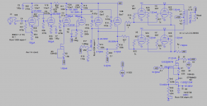
I've build my self a new pair of inefficient speakers (approx 83db/1w)... So I need a replacement for my 10w monoblocks. Looking for something with more power I came across the following website 50 watt monoblock amplifier.
I'd like to reduce the number of tubes used in this build. The a02 can be replaced by zeners but what solid state alternative can I use to replace the 6BH6 and 6CL6 pentode's?
Attachments
A DN2540 cascode CCS will work great and reduce the amount of negative voltage needed.
For the pass devices, I'd use any big, hairy 1000V 100W (or more) MOSFET.
I'm rather surprised that he only got 50W out of 4 6L6GC in pentode. In any case, an alternative you might look at is the 50W amp in the RCA tube manual, which is chock full of good design ideas. That said, the designer of the circuit you posted got a lot right, so kudos to him.
A DN2540 cascode CCS will work great and reduce the amount of negative voltage needed.
For the pass devices, I'd use any big, hairy 1000V 100W (or more) MOSFET.
I'm rather surprised that he only got 50W out of 4 6L6GC in pentode. In any case, an alternative you might look at is the 50W amp in the RCA tube manual, which is chock full of good design ideas. That said, the designer of the circuit you posted got a lot right, so kudos to him.
Thanks SY, for your reply. I've been googling but I guess I need some more specific help. Looking at the DN2540 datasheet but I'm not sure were to start. Never worked with MOSFETS before...
Thanks SY, for your reply. I've been googling but I guess I need some more specific help. Looking at the DN2540 datasheet but I'm not sure were to start. Never worked with MOSFETS before...
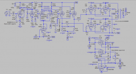
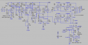
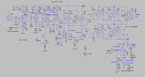
How about this? You can use other MOSFET. The gain is too high, the front end stage can be omitted.
Attachments
Last edited:
Thanks SY, for your reply. I've been googling but I guess I need some more specific help. Looking at the DN2540 datasheet but I'm not sure were to start. Never worked with MOSFETS before...
Those cascodes have been discussed here a lot- a quick forum search should turn up a lot of hits. AFAIK, the first published mention was my Impasse article in AudioXpress (which you can download from my website). They're also used in the His Master's Noise phono stage in the Articles section of this site. You can find further info in Morgan Jones's "Valve Amplifiers" 4th edition and "Designing High Fidelity Tube Preamps" by Merlin Blencoe.
How about this? You can use other MOSFET. The gain is too high, the front end stage can be omitted.
Holy 😱😱😱
Thanks!
But then again, I'm still not sure how this is working. Would you mind sharing your asc file?
Thanks SY, I'm reading your article now 🙂 "There is relief at hand—depletion-mode MOSFETs are becoming easier to get, and the DN2540 is cheap, available, and works perfectly in this service."
See attached. I forgot to add NFB loop earlier, so now it's added, then there is no mentioned of the feedback level, so I just reduce it about 10 dB, the gain now looks reasonable. The solid state regulator is far superior to tube in turn of "ripple rejection", 1000mV/15mV ratio at +B2 regulated output, that is measured while the amp delivered about 50W 1khz out.
Attachments
Last edited:
See attached. I forgot to add NFB loop earlier, so now it's added, then there is no mentioned of the feedback level, so I just reduce it about 10 dB, the gain now looks reasonable. The solid state regulator is far superior to tube in turn of "ripple rejection", 1000mV/15mV ratio at +B2 regulated output, that is measured while the amp delivered about 50W 1khz out.
great! a hundred times thank you!
I read the original description for the amp again and it says the following about the feedback:
The values of the resistor Rf and capacitor Cf depend on which output transformer you are using.
Transformer
Hammond Rf=910ohms Cf=0.0022microfarads
Edcor Rf=1200ohms Cf=0.0018microfarads
Here the asy and sub file in use, rename the file before use.
Thanks again! Finally got it to open, not with the same result though.. in a previous post you said you added 10db NFB, but where? it's not in the schematic is it?
Attachments
Last edited:
Thanks again! Finally got it to open, not with the same result though.. in a previous post you said you added 10db NFB, but where? it's not in the schematic is it?
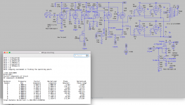
NFB resistor is Rf, near R10, in actual sch is R10 is 390, not 390k, which is 10x, so Rf is 1Meg. The result of NFB is same. When I change R10 to 390 and Rf changed to about 1k, there is oscillation, so I think you stick with R10 as 390k. You can remove/add Rf to check the open loop gain and close loop gain, check with level in db with AC analysis.
NFB is not added to orginal sch, that is right, only to mod sch, try to add yourself.
Ok I have some more questions before I am going to commit to building this amp. Am I correct that when I measure 24.40V on the output of the amp.
This translates to
RMS Power = (V*V) / R_Load
= (24.40*24.40) / 8
= 74.42 Watt
that's a bit more than the 50W the designer is talking about and the Hammond 1650K he uses won't be enough...
I was going to order custom toroidal output transformers and if I'm correct they have to be at least rated for 75Watts?
The OPT in the uses lower primary impedance that is less than 3.5k of 1650k, so the power is higher. For parallel 6L6 maybe 3.5k is not optimal load. Fender guitar amp Bassman 6L6 PPP gives 100 Watts. http://www.thevintagesound.com/ffg/schem/bassman_135_schem.jpg so maybe 75 Watts is a good choice considered HT is only 400V.
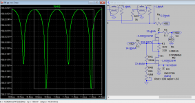
Edit with pri 40H *2 and sec. 0.18H, I only get 18V rms which is about 40W, 75W when sec is 0.3H. Please check again using attached 6l6 model.
Edit with pri 40H *2 and sec. 0.18H, I only get 18V rms which is about 40W, 75W when sec is 0.3H. Please check again using attached 6l6 model.
Attachments
Last edited:
I'm rather surprised that he only got 50W out of 4 6L6GC in pentode.
Not at all surprising since this looks like Class A1 operation. 50W here would be what I'd expect from a quad of 6L6s.
- Status
- Not open for further replies.
- Home
- Amplifiers
- Tubes / Valves
- 50W 6L6 (6P7S) how to replace tube ccs for solid state?