There's almost certainly a hundred or more pF of stray capacitance to mains via the transformers in your power supplies, depending on the construction of the trafos. Perhaps what's happening is that in the -134dB case the leakage (due to capacitive coupling) is being shunted to ground somewhere and in the -119dB case it isn't.
Sorry to bump this thread again but I just can't get to the bottom of this issue. I'm think I've implemented the ADuM IC incorrectly perhaps?
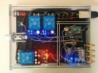
I've tidied all my cabling. It is now twisted and as short as possible:
http://www.diyaudio.com/forums/atta...-volume-input-control-img_20140704_183003.jpg
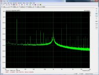
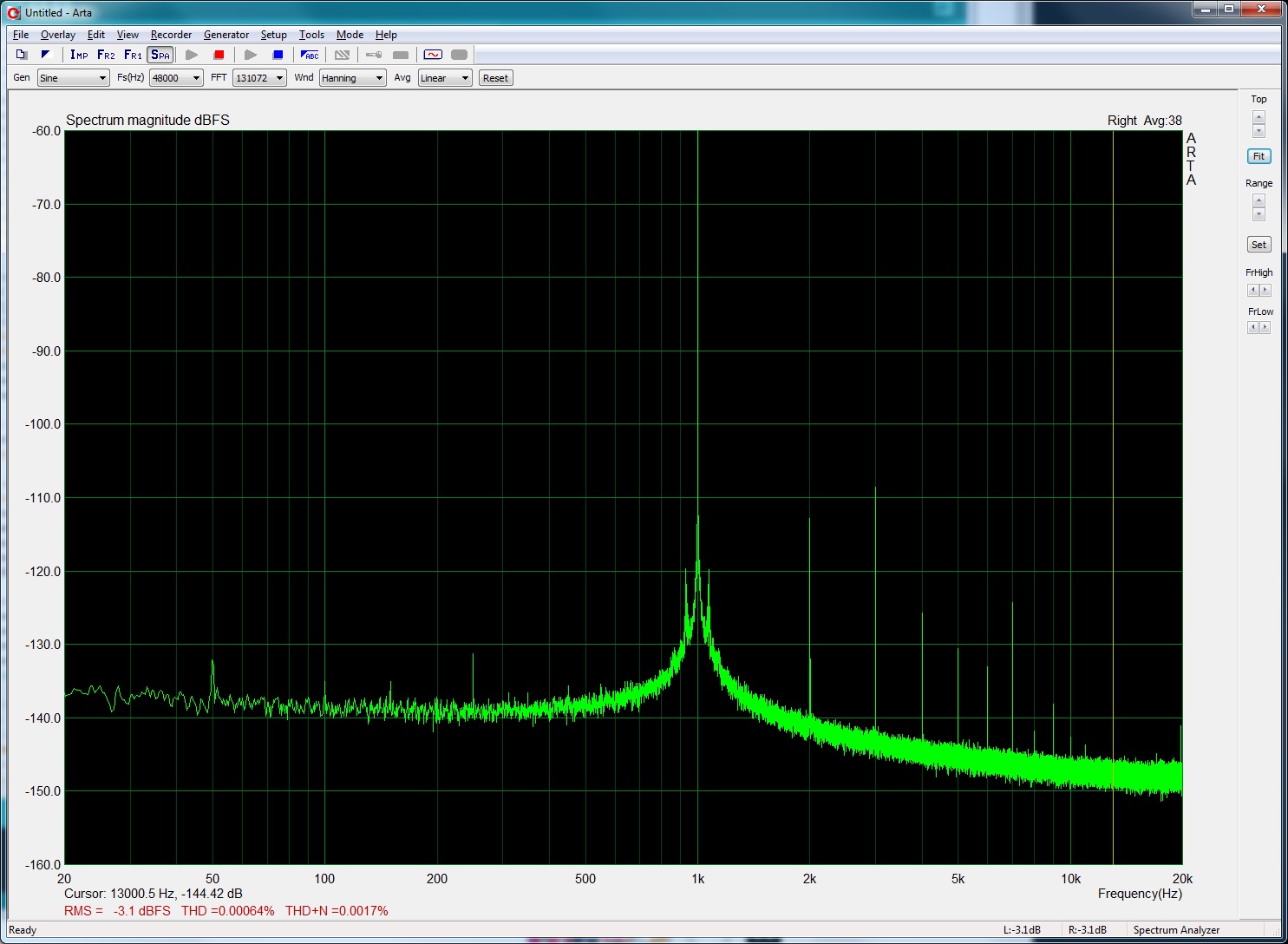
And still using a single 5V PSU I can get good measurements:
http://www.diyaudio.com/forums/atta...uino-remote-volume-input-control-untitled.jpg
But when I use both 5V PSUs with each side of the ADuM isolator IC separate I have the following issues:
- 50hz spike
- Worse measurements
- 10dB more gain.
I didn't realise the gain increase before so perhaps it's something to do with the +/- PSU that powers the IV opamp? I've attached new measurements. Using a battery to power the Arduino together with either of the 5V PSUs works great but both 5V PSUs together seems to ruin it. It must be something silly or simple I've done!
I've tidied all my cabling. It is now twisted and as short as possible:
http://www.diyaudio.com/forums/atta...-volume-input-control-img_20140704_183003.jpg
And still using a single 5V PSU I can get good measurements:
http://www.diyaudio.com/forums/atta...uino-remote-volume-input-control-untitled.jpg
But when I use both 5V PSUs with each side of the ADuM isolator IC separate I have the following issues:
- 50hz spike
- Worse measurements
- 10dB more gain.
I didn't realise the gain increase before so perhaps it's something to do with the +/- PSU that powers the IV opamp? I've attached new measurements. Using a battery to power the Arduino together with either of the 5V PSUs works great but both 5V PSUs together seems to ruin it. It must be something silly or simple I've done!
Attachments
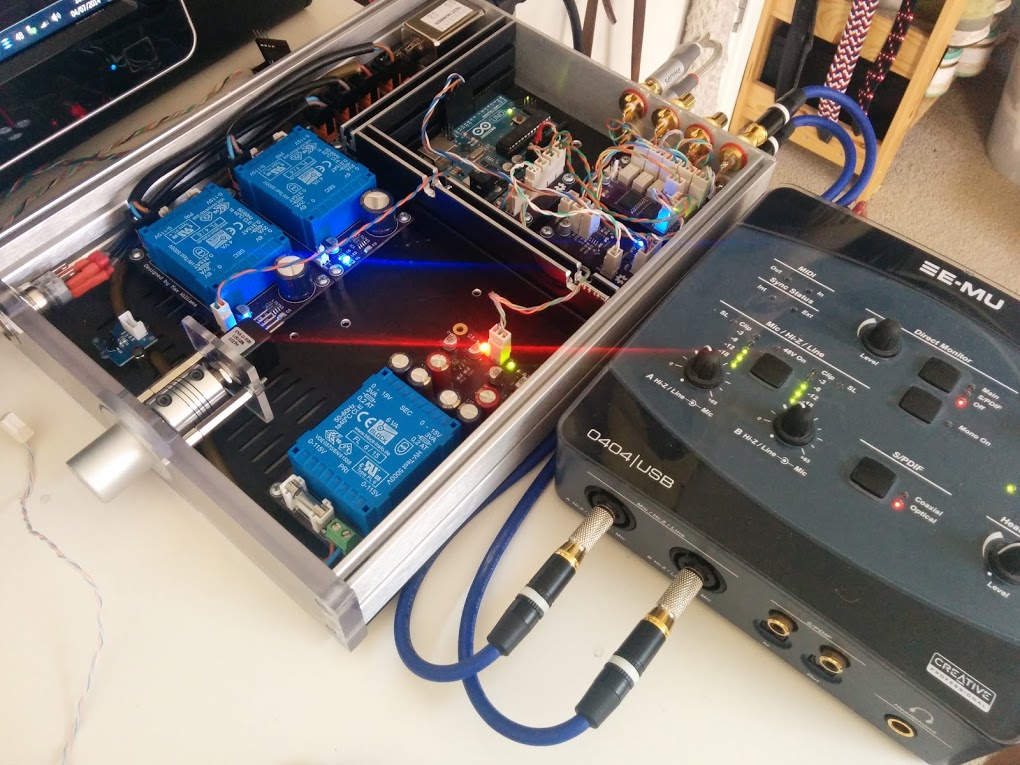
Is your chassis connected to ground? It looks like the earth tab of your IEC inlet isn't connected to anything.
Is your chassis connected to ground? It looks like the earth tab of your IEC inlet isn't connected to anything.
Yeah, it's connected through the metal body of the socket. I've tested every single piece of the chassis and every screw and they are all earthed.
Signal ground is not connected to the chassis though.
Here's a bigger picture of the cabling.
Attachments
- Status
- Not open for further replies.