Greetings and all of that. I have a very basic question, and seem to not be able to find the answer. I am attempting to run a pre amp of my own creation (12FQ8, with which I am having problems as well) or maybe just something from on of the DIY shops in China (6N3) into a 50c5 and need a very basic instruction, dumbed down for Homer Simpson. We could just assume Homer is my better in everything electronic for this
My name is Gerry, and I am new here, and would like to bid all of you a sound and resounding, "Hello." Maybe I can help any of you with something. I use to record and work A&R for a mid sized indie label.
Thank you all very much.
My name is Gerry, and I am new here, and would like to bid all of you a sound and resounding, "Hello." Maybe I can help any of you with something. I use to record and work A&R for a mid sized indie label.
Thank you all very much.
What is a 50C5? It sounds like it ought to be an output valve in a cheap AC/DC 1950's radio.
What do you need instructions for? To get an answer, first you need to have a clear question.
What do you need instructions for? To get an answer, first you need to have a clear question.
I don't think it is a cheap 1950s radio, as it has 7 tubes, but it is a cheaper version, if that makes any sense.
The 50c5 vacuum tube data sheet says that the 50c5 is a output power tube, close in construction to the 35c5. I am looking for how to get audio into the tube, and from whence I should pull it out. It is a seven pin, and again very closely natured to the 35c5 output tube. There is a 12au6 in line, and when I tried to substitute it for a 12av6, it hummed something fierce. Being as how I am new to this field of study, all of these are new to me. The tubes are as follows: 12DT8 (I think this is a buffer tube), 2x the common 12BA6, 12BE6, the aforementioned 12AU6, 14GT8, and 50C5. I am hoping to turn this into a guitar amp, but I will be content to just use the FM portion and broadcast the very weak signal for around the house.
My specific question is about the 50C5 power tube regarding how to use that effectively in another, home made amp. Can I use any power tubes from any radio to make a low powered amp? If one would be so kind as to send me a schematic, it would prove more of an act of charity to also include instructions. And if one could throw in the instructions and schematic for a pre amp stage, in line with that. Thanks to all who take pity upon me.
12BE6 is a pentagrid converter for RF, useless.
12BA6 is a remote cutoff pentode which would generate a good bit of distortion if used for audio. Also useless.
12DT8 is a high mu twin triode for RF. Can be used for audio.
12AU6 sharp cutoff pentode. Can be used for audio.
14GT8 is a duplex-diode and triode. The triode is useful for audio.
6AV6 is a duplex-diode and triode. The triode is useful for audio.
50C5 is a audio output Beam Pentode good for 1.9W output.
Looks like you have the remnants of a radio.
You can't arbitrarily substitute tubes. You need to look up the tube datasheets and understand what they were designed for and their pin-outs before swapping them.
You need to use a transformer to power the tubes, and isolate their circuit from the line voltage for safety reasons.
I suggest you read through the stickies at the top of the list and do some reading before proceeding further as you lack the necessary education at this point in time. You can gain this quite easily by reading the information made available.
http://www.diyaudio.com/forums/tubes-valves/38278-line-tube-learning-newbies.html
http://www.diyaudio.com/forums/tubes-valves/30172-safety-practices-general-ultra-high-voltage.html
Normally the 50C5 is used in US AM radios with a series-connected heater string directly across the AC line, with no power transformer.
Methinks Homer may electrocute himself if this is the case...
Seriously, if that is the case (there is no power transformer) you are flirting with disaster. Not to mention it is a forbidden topic here.
Pete
Methinks Homer may electrocute himself if this is the case...
Seriously, if that is the case (there is no power transformer) you are flirting with disaster. Not to mention it is a forbidden topic here.
Pete
Sounds like a late 50's or early sixties AM/FM tube set - Magnavox maybe. If you look at the first numbers of all the tubes - that is their heater voltage. The heaters are strung in series and wired directly to the AC line which makes the set dangerous to both you and your equipment. Add up all the voltages and you get 118 VAC.
You can make an amp with a 50C5 but one would wonder why you would want to. RCA used to make cheap 12AX7 dual 50C5 PP amps for their 45 players. Notorious for hum because of heater cathode leakage. If you want to find a use for these tubes, the antique radio forum would probably be of more use. Or you could just put them back in the radio, recap it and listen to FM.
Is AC/DC series string stuff a forbidden topic here? If so, please delete my post.
Series heater strings are allowed. Direct connection to the mains is not.
OK, at least I now understand the question. I originally thought the 50C5 might be an amp (as only an amp would need a preamp in front of it). We now know that the OP wants to put a voltage amplifier in front of an output stage to make an amplifier. Best advice is find and read the Valve Wizard website and/or buy and read the book by Morgan Jones. Actually, best advice is to find a more suitable output valve.
This is one of those tasks where if you need detailed instructions then the task is beyond you, at your current state of knowledge and experience. Buy a kit. That's where most of us started.
I am attempting to explain this as simply as possible.
Would you take a wire, connect one end of it to your guitar, and stick the other end into the wall outlet? I hope not! Attempting to make a guitar amp from an old radio may be doing EXACTLY THAT!
The tubes you listed were used in common radios from the late 50s through the 1960's. Common wisdom of the day believed that people shouldn't be sticking their hands inside an electrical appliance that was plugged into the wall outlet, so most of the budget radios and many TV's were directly connected to the wall outlet. The metal guts and all of the circuitry were live, but insulated from the user by a wood or plastic case. The circuitry inside ANY radio with a 50C5 inside it was powered directly from the wall outlet with no means of preventing shock to the user other than that plastic case! People were KILLED by nothing more than a broken or missing knob.
Connecting a guitar cord to ANYTHING inside that plastic (or wood) case is electrically equivalent to sticking your guitar cord into the wall outlet.
Note to readers:
It is possible to add an isolation transformer and a 3 prong cord to an old radio or other "hot chassis" product to make it safe. You MUST UNDERSTAND what you are doing to avoid a continued shock hazard! The strings on your guitar are steel, and usually connected to the ground side of the guitar cord to reduce hum. You place your left hand around the neck in a manner that will guarantee not being able to let go of the guitar while being shocked until you are DEAD and cooked! Do your hands get sweaty after thrashing a guitar for a hour or two on a hot stage? People have been KILLED from a hot (electrically) guitar or microphone.
It may be technically possible to make a guitar amp from such a safety enhanced radio, but there wouldn't be enough gain for any real good "tone." I tried this way back in the 60's.
There WERE some guitar amps made in the 50's and 60's that ignored all of this and attempted to isolate the guitar player from the power lines with a 10 cent wax and paper capacitor........Same results. Google "death cap electronics."
If you find an old guitar amp with a 50C5, 35C5,25C5, 50L6, 35L6, or 25L6 in it DO NOT plug it in until you or someone who understands the risk verifies that there is transformer isolation from the mains, power line, wall outlet, or whatever you call the receptacle you plug things into!
My first guitar amp was a Magnavox record player. I simply twisted the wires from a guitar cord to the wire in the tone arm on an old Magnavox record player console from the 1950's wen I was about 9 or 10 years old. It had enough gain to play loud, and it made about 10 watts from a pair of 6V6's.
If you find an old record player from the 50's that has all the tubes starting with a 6 or 12, and VERIFY that it has a good transformer in its power supply, then this may be a valid option. If you don't know how to do this, have someone who does look it over......getting fried SUCKS.
http://en.wikipedia.org/wiki/Keith_Relf
https://en.wikipedia.org/wiki/Leslie_Harvey
Last edited:
Th 12FQ8 is a really strange tube, usually used for tone generator/frequency divider duty in organs. It has a split plate for each triode instead of one like normal triodes.
I'm with DF96 on this one. It would be best to learn some basics before trying to do too much, especially with tubes not normally used in common amps. The 6AV6 is the only tube I recognize as useful in easy to understand amp designs and even that tube has two diodes that are usually just grounded and not used.
These tubes probably came from an AAF(All American Five) radio from the1950s. Most were designed for Radio Frequency duty. They would be useful to someone with more experience to build a guitar amp from.
These tubes probably came from an AAF(All American Five) radio from the1950s.
They did come from a radio. It was basically an AA5 with added FM.
12DT8 (I think this is a buffer tube),
The 12DT8 is used as the FM RF front end in a radio. It is actually a dual triode not too different from a 12AT7, and yes you can use it in a guitar amp.
The 12FQ8 did not come from a radio, it is from an organ. You an wire all 4 plates in parallel and use it as a single triode, but why?
It is possible to make an amp, even a guitar amp from ALMOST any tubes (good luck with 1B3's or 6AL5's), but sometimes it isn't worth the hassle when there are plenty of cheap tubes that will work good!
The 50C5 requires 50 volts to light it's heater. If you aren't feeding it 50 volts you won't get far. Pick a "power tube" that has a 6 or 12 volt heater. Good examples of cheap ones are the 6AQ5, 12AQ5, 12L6, 12V6, 6CU5, and the 12DB5.
See the Hundred Buck Amp Challenge thread at the top of this forum for some ideas, including my guitar amp made with old radio tubes....yes it has an isolation transformer. I have updated it since that thread, but it is stuck n a box somewhere since my recent move.
They did come from a radio. It was basically an AA5 with added FM.
The 12DT8 is used as the FM RF front end in a radio. It is actually a dual triode not too different from a 12AT7, and yes you can use it in a guitar amp.
The 12FQ8 did not come from a radio, it is from an organ. You an wire all 4 plates in parallel and use it as a single triode, but why?
It is possible to make an amp, even a guitar amp from ALMOST any tubes (good luck with 1B3's or 6AL5's), but sometimes it isn't worth the hassle when there are plenty of cheap tubes that will work good!
The 50C5 requires 50 volts to light it's heater. If you aren't feeding it 50 volts you won't get far. Pick a "power tube" that has a 6 or 12 volt heater. Good examples of cheap ones are the 6AQ5, 12AQ5, 12L6, 12V6, 6CU5, and the 12DB5.
See the Hundred Buck Amp Challenge thread at the top of this forum for some ideas, including my guitar amp made with old radio tubes....yes it has an isolation transformer. I have updated it since that thread, but it is stuck n a box somewhere since my recent move.
Or you can make this.
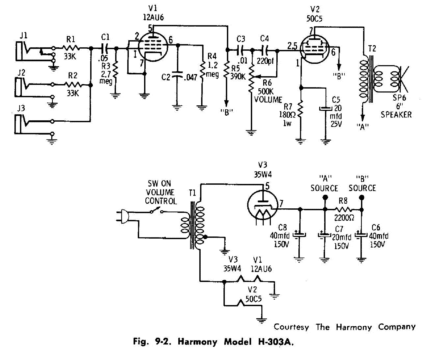
with a decent sensitive speaker it sounds amazing, check it out on youtube there are many demos.
I used a 117v primary to 100v 150mA for the heaters and 200v 70mA for the amp.
Accordingly to my RCA manual (link below) the 50C5 will hold up well up to 150v for plate, 130v for the screen, 7 W anode dissipation. I used a 4k to 8 ohms output transformer and got about 3 watts rms.
http://frank.pocnet.net/sheets/191/5/50C5.pdf
That H-303A scheme shows R4 grounded. Boo boo, no?
I have a Silvertone 1451 which is very similar in circuitry, albeit with no power tranny from the factory. I added the ISO to avoid the wall.
I have a Silvertone 1451 which is very similar in circuitry, albeit with no power tranny from the factory. I added the ISO to avoid the wall.
Or you can make this........with a decent sensitive speaker it sounds amazing
Not the way it is drawn, in fact it won't even work. The screen grid resistor on the 12AU6 is connected to ground, it should connect to "B".
I used a 117v primary to 100v 150mA for the heaters and 200v 70mA for the amp.
If so, you would connect all of the heaters in series.
The unusual transformer used in that amp is rather hard to find. There are other ways to do this that are more common today.
As I stated earlier, my first amp was a Magnavox HiFi. Within a few years I had learned to make my own amps. The circuit for that Kay amp came from the same place that I started from in the mid 1960's, the Fender Champ 5C1.
Google "Fender Champ 5C1 schematic" and you will find a rather simple design that is very similar to the Kay, but it uses more conventional tubes and transformers. I made these things from old radio and TV parts scavenged from the local landfill. All of the tubes use 6 volt heaters, although I built some 12 volt versions.
The 6SJ7 was a common radio tube from the 40's and 50's, but isn't too common today. Almost ANY small pentode from a radio or TV set will work. 6SJ7, 6SK7, 6AU6, 6BA6 are the common 6 volt radio tubes. The 12 volt versions will work too if a suitable power transformer is used. The Kay used a 12AU6.
The 6V6 was a common radio tube in the 40's and 50's too, and it is still made today, but because it is used in a guitar amp, it can not be found cheap. Even in the 60's the 6V6 was often missing from the radios and HiFi sets in the trash dump. I used 6K6's 12V6's 6AQ5's 12AQ5's 6EZ5's and 6BQ6's. My favorite combination was a 6SJ7 and a 6BQ6.
The output transformer can be the OPT from nearly any radio or TV set, and in some cases the vertical sweep transformer from a TV would work. I salvaged power transformers and rectifier tubes from old radios too. Today I would use an Antek toroid and a 6X4, 6X5, 12X4, or 6BY5 rectifier.
If the builder wants to spring for a 12AX7 the Champ 5F1 is another easy choice. I made several of these too.
yes sir, if I recall correctly I made that mistake while building it and then fixed it immediatly.Not the way it is drawn, in fact it won't even work. The screen grid resistor on the 12AU6 is connected to ground, it should connect to "B".
it's true winding your own transformer takes time, materials & patience.If so, you would connect all of the heaters in series.
The unusual transformer used in that amp is rather hard to find. There are other ways to do this that are more common today.
. 6SJ7, 6SK7, 6AU6, 6BA6 are the common 6 volt radio tubes. The 12 volt versions will work too if a suitable power transformer is used. The Kay used a 12AU6.
what about 6CG6 and 6AG5 ? have you tried them ?
6CG6, no I don't have any of them.
6AG5, yes, I had a bunch of them and they generally work good here.
I must state that the Fender Champ and the Kay schematics both used grid leak bias on the input tube to save a few cents in parts cost. That was OK in the 40's, but is not the preferred method today.
Grid leak bias connects the cathode directly to ground and used a large value resistor (over 1 meg) to "leak off" a prescribed amount of grid current to create a negative voltage on the grid. This works great in theory, but we are often working with tubes that are 50 or more years old that may have some minor air intrusion or "gas" contamination. This will also leak off some more grid charge, thereby changing the bias voltage. This makes the circuit more susceptible to tube to tube variation.
The preferred method is to connect the grid to ground through a 100 K or so resistor and use a resistor in series with the cathode to generate a positive voltage on the cathode.
Thanks for all your participation. My growing knowledge is requiring more questions, which is a good thing. I am getting the feeling that if I were to have plugged my guitar into the phono jack on the first purchased, I would have quite probably fried myself, so thanks for that, too.
I am studying how to read schematics, and so I feel mostly confident, and can ask elsewhere. I am not understanding fully the difference between the heater, running just as a heater, and the voltage, or B+. I do need to heat the filament AND run the plate current, 50, 110, or possibly up to 300. From whence does the 300 volts come? A second transformer? Is this a step up transformer?
The $100 challenge, I can't seem to find it. Thanks for all the help, and I can't wait until I am answering other new guys questions, in some time.
I do need to heat the filament AND run the plate current........From whence does the 300 volts come? A second transformer? Is this a step up transformer?
It can be done with two transformers, and it is done this way by some DIY builders. It is possible to build a transformer with one primary and two or more secondaries. In the case of the Fender Champ there is one primary, two step down secondaries, one for the rectifier heater (filament) 5 volts, another for the other heaters 6.3 volts, and a step up secondary to supply the high voltage for the tube plates.
if I were to have plugged my guitar into the phono jack on the first purchased, I would have quite probably fried myself
It is possible that you would receive a mild shock IF the old isolation capacitor is good, and much worse if it has failed. I wouldn't trust my fate to some 50+ year old part.
The old radios wired all the tube heaters in series and connected them all to the wall power source. This requires all the tube heater voltages to add up to 117 volts (or close). They also get the B+ (plate supply voltage) by directly rectifying the power line voltage. Special tubes were designed with heater voltage optimized for power line use, and plate voltages optimized for 130 to 160 volts like the 50C5.
This allows elimination of the power transformer for cost, size and weight savings, but unfortunately kills people. The practice continued well into the solid state era, and is pretty much discontinued today due to the use of modern SMPS (digital) power supply technology.
Note, circuitry INSIDE these power supplied IS directly powered from the power lines.....don't open them up and mess with the insides, or modify them unless you fully understand what's going on. Even if you can avoid getting shocked, parts connected directly to the power lines can violently explode if provoked!
- Status
- Not open for further replies.
- Home
- Live Sound
- Instruments and Amps
- 50C5 for a Newbee.