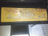
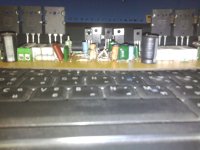
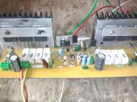
hi Apex.. my second module there is a problem of high noise barrier disposable clip LED LDR but not yet installed( in my place very difficult to provide NSL-32), if this is provoking noise and gain over a rough bass voice also drowned unlike previous modules bass, mid, Hight transparent and smooth bass,,, please provide solution ( sorry the picture not clear )
First Modul very nice
second modul problem quality audio not smooth
An externally hosted image should be here but it was not working when we last tested it.
First Modul very nice
An externally hosted image should be here but it was not working when we last tested it.
second modul problem quality audio not smooth
Last edited:
hi Apex.. my second module there is a problem of high noise barrier disposable clip LED LDR but not yet installed( in my place very difficult to provide NSL-32), if this is provoking noise and gain over a rough bass voice also drowned unlike previous modules bass, mid, Hight transparent and smooth bass,,, please provide solution ( sorry the picture not clear
First Modul very nice
second modul problem quality audio not smooth
I don't see NE5532, can you post clear pictures, and measure voltages on test point as I suggest for H900. Amp can work without NSL32.
Asking for a little help
Hy! Apex, if you are not too busy, could you help me please?
I started to build my amp, first of all, i soldered the protection circuit. I wanted to try it only with giving it 2x18VAC and connecting the BD241 as heat sensor. The fan started to work at 12V, but as i slowly heated the BD241, it remained slow, and sometimes, when i plug the transformer to mains, the relay immediately turns on, and the prot. led isn't working. I checked every resistor before i soldered them in, and every transistor and all the components, now i am stuck. Is it a possible problem, that i used ceramic capacitors for the 0,1uf ones?
And one more thing: If i disconnect one of the AC 18V supply lines, the relay and the fan remains on.
Thanks, and sorry to disturb you
Last edited:
Hy! Apex, if you are not too busy, could you help me please?
I started to build my amp, first of all, i soldered the protection circuit. I wanted to try it only with giving it 2x18VAC and connecting the BD241 as heat sensor. The fan started to work at 12V, but as i slowly heated the BD241, it remained slow, and sometimes, when i plug the transformer to mains, the relay immediately turns on, and the prot. led isn't working. I checked every resistor before i soldered them in, and every transistor and all the components, now i am stuck. Is it a possible problem, that i used ceramic capacitors for the 0,1uf ones?
And one more thing: If i disconnect one of the AC 18V supply lines, the relay and the fan remains on.
Thanks, and sorry to disturb you
Measure voltages +/-15V, and you must have 500mV on BD241C (thermal diode) on 25 deg, and drop 2mV per deg. First comparator (400mV) turn on 24V to fun, and second (350mV) cut out speaker. Measure reff voltages on comparators inputs.
Regards
Module who had met yesterday problematic culprit of the problem is the resistor pairs, now B500-2 module to the great sound and bass, mid, treble, transparent, who really just hesitate to make the pole 15volt Zener voltage (-) v 9.7, polar (+) 8.2V ct travo 50V supply voltage difference occurs 1.5v 30a R24/25 2k7/2W whether erosive voltage difference, .. what the risk is on the performance of power ... what part of that must be corrected
greetingListen
Read phonetically
An externally hosted image should be here but it was not working when we last tested it.
greetingListen
Read phonetically
Last edited:
Module who had met yesterday problematic culprit of the problem is the resistor pairs, now B500-2 module to the great sound and bass, mid, treble, transparent, who really just hesitate to make the pole 15volt Zener voltage (-) v 9.7, polar (+) 8.2V ct travo 50V supply voltage difference occurs 1.5v 30a R24/25 2k7/2W whether erosive voltage difference, .. what the risk is on the performance of power ... what part of that must be corrected
greetingListen
Read phonetically
greetingListen
Read phonetically
An externally hosted image should be here but it was not working when we last tested it.
Module who had met yesterday problematic culprit of the problem is the resistor pairs, now B500-2 module to the great sound and bass, mid, treble, transparent, who really just hesitate to make the pole 15volt Zener voltage (-) v 9.7, polar (+) 8.2V ct travo 50V supply voltage difference occurs 1.5v 30a R24/25 2k7/2W whether erosive voltage difference, .. what the risk is on the performance of power ... what part of that must be corrected
greetingListen
Read phonetically
An externally hosted image should be here but it was not working when we last tested it.
Add resistors 2k7/2W in parallel with existing. CCS use voltage on serial conection of two 1N4148 diode, and can work with 8-9V but better go to 15V.
Regards
how about the difference between the phase voltage (-) and (+)..? whether there was no influence on the performance of power, because the driver was hot if it was normal ...
thanks
thanks
how about the difference between the phase voltage (-) and (+)..? whether there was no influence on the performance of power, because the driver was hot if it was normal ...
thanks
MJE340/MJE350 must have heatsink (disipate 0,5-1W). Increase voltage on zeners to 15V with add 2k7/2W, and there will be no difference.
Regards
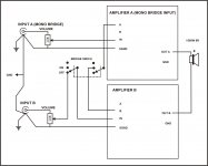
Could sir b500 & H900 combined with the BTL system because I need a large power for field application recomendations please
thanks
thanks
Last edited:
Could sir b500 & H900 combined with the BTL system because I need a large power for field application recomendations please
thanks
Post #220 in H900 thread.
Regards
Attachments
Problem solved
Hy Apex! I think the problem is solved. I was too tired, when i measured the circuit, and i used an old 24V fan, and for some reason, it didn't change its speed when the circuit gave 24V. Anyway, today i completed another protection circuit, and it works very well(i think). Here are my measures:
625mV on BD241C at 25 degC, fan gets 12V
When it drops to 440mV, fan gets 21V (i don't know, why not 24?) at this point i could barely touch the BD241C
At 340mV the protect led comes on, and the relay turns off.
As the component cools down, the relay turns back on.
Thanks for the help.
I post as soon as i can put pictures here, and now i start to make the B500 boards.
Bye
Measure voltages +/-15V, and you must have 500mV on BD241C (thermal diode) on 25 deg, and drop 2mV per deg. First comparator (400mV) turn on 24V to fun, and second (350mV) cut out speaker. Measure reff voltages on comparators inputs.
Regards
Hy Apex! I think the problem is solved. I was too tired, when i measured the circuit, and i used an old 24V fan, and for some reason, it didn't change its speed when the circuit gave 24V. Anyway, today i completed another protection circuit, and it works very well(i think). Here are my measures:
625mV on BD241C at 25 degC, fan gets 12V
When it drops to 440mV, fan gets 21V (i don't know, why not 24?) at this point i could barely touch the BD241C
At 340mV the protect led comes on, and the relay turns off.
As the component cools down, the relay turns back on.
Thanks for the help.
I post as soon as i can put pictures here, and now i start to make the B500 boards.
Bye
Good luck with B500,
Regards
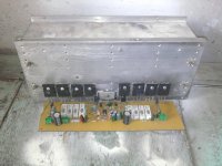
Getting closer to finish
Hy! I post some pics, comment it if you want.
Apex: I modified the protect board, i hope you don't mind. I used my favorite relay, and so the board needed to be modified.
I also made a psu, 80.000uf/100V total, i hope this is enough for 2 of this B500 amplifiers.


Hy! I post some pics, comment it if you want.
Apex: I modified the protect board, i hope you don't mind. I used my favorite relay, and so the board needed to be modified.
I also made a psu, 80.000uf/100V total, i hope this is enough for 2 of this B500 amplifiers.
Hy! I post some pics, comment it if you want.
Apex: I modified the protect board, i hope you don't mind. I used my favorite relay, and so the board needed to be modified.
I also made a psu, 80.000uf/100V total, i hope this is enough for 2 of this B500 amplifiers.
I like your work, I share all this schematics to be use, and to be upgrade, improve, modified...
Regards
hi apex
sir in my project i have little problem.....in low volume audio is not clear,and when i start the amp it sound like ttrrrrrrr....
sir in my project i have little problem.....in low volume audio is not clear,and when i start the amp it sound like ttrrrrrrr....
hi apex
sir in my project i have little problem.....in low volume audio is not clear,and when i start the amp it sound like ttrrrrrrr....
Do you use suggested ground wireing, and do you measurment voltage at suggested point?
Heii..Apex..I found problem on B500. Like this:
I used PSU +/-44VDC, If I not applied fuse, I measure voltase (+) and (-) to ground is simetris (44 vdc), also (+) and (-) to output power is simetris (44 vdc). But when I used fuse 10A, voltase (+) and (-) to ground not simetris, (+) to ground = 43vdc and (-) to ground only 35 vdc. Also (+) to out PA only 35vdc and (-) to out PA= 43 vdc.
If I used fuse 0,2A, voltase (+) to ground = 43vdc and (-) to ground = 42,3vdc. Also (+) to out PA=42,3vdc and (-) to out PA = 43vdc..
Please help me..
Regards
- Home
- Amplifiers
- Solid State
- 500W PA amplifier with Limiter