Project 3A
Hello
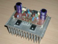
I made my ovn PCB for the Project 3A.
The sound is great, but the power i limited.
It's great for a smaller system and biamping.
There is an option enabeling bridged mode opration
Build it !
🙂
Hello
I made my ovn PCB for the Project 3A.
The sound is great, but the power i limited.
It's great for a smaller system and biamping.
There is an option enabeling bridged mode opration
Build it !
🙂
REALLY, REALLY BAD IDEA!!
REALLY, REALLY BAD IDEA!!
ALWAYS use fuses. They won't protect your output transistors, but once the transistors go s/c they stop your power supply catching fire and burning the house down. This may then necessitate you running out into the street in your undies in the middle of the night while the whole neighbourhood is watching.
Your insurance company also may not want to cooperate if they find your amp is not even remotely UL certified or whatever thing is equivalent is your country.
GP.
hugobross said:DON'T use fuses to protect your transistors, they are simply too slow to handle short circuits.
REALLY, REALLY BAD IDEA!!
ALWAYS use fuses. They won't protect your output transistors, but once the transistors go s/c they stop your power supply catching fire and burning the house down. This may then necessitate you running out into the street in your undies in the middle of the night while the whole neighbourhood is watching.
Your insurance company also may not want to cooperate if they find your amp is not even remotely UL certified or whatever thing is equivalent is your country.
GP.
PCB SW
Hi Vivek
I use a program called Eagel
It has both a schmatic and a pcb program, working together
It's freeware
Mail me for details 😉
Hi Vivek
I use a program called Eagel
It has both a schmatic and a pcb program, working together
It's freeware
Mail me for details 😉
Project 3a sounds pretty good but be warned.... if you build it "as is" when something goes wrong you'll almost certainly lose the output transistors and speakers. Fuses in line with the speakers are only moderately effective. I guess it's not bad if you speakers are worth $50 but I wouldnt be plugging your latest greatest diy speakers up to one of these.
Jens,
Good for you.
Audiofreak,
You sounded the alarm bells by mentioning that the speakers may be affected. My DIY speakers are not very expensive but nevertheless, I would not like to have my speakers puffing smoke instead of sound. After all, I have put in a substantial amount of work. Maybe I should re-consider my amp plans.
Regards,
Vivek
IMPORTANT
Yep Ciclotron,
I justed wanted to tell fuses are not sufficient to protect the transistors, I didn't want to tell to leave them away!
I'M SORRY TO BE SO UNCLEAR!!!
ALWAYS USE FUSES IN AMPS OR OTHER DEVICES WHICH ARE CONNECTED TO THE MAINS OR WHICH HANDLE HIGH POWER!!!
I MUST thank you for this reply!!!
HB.
ALWAYS use fuses. They won't protect your output transistors, but once the transistors go s/c they stop your power supply catching fire and burning the house down. This may then necessitate you running out into the street in your undies in the middle of the night while the whole neighbourhood is watching.
Yep Ciclotron,
I justed wanted to tell fuses are not sufficient to protect the transistors, I didn't want to tell to leave them away!
I'M SORRY TO BE SO UNCLEAR!!!
ALWAYS USE FUSES IN AMPS OR OTHER DEVICES WHICH ARE CONNECTED TO THE MAINS OR WHICH HANDLE HIGH POWER!!!
I MUST thank you for this reply!!!
HB.
Fuses
All my circuits have been simulated in spice including the project 3A
(I found an error in the circuit this way)
I newer use a fuse in series with the output as it affects the sound.
If the fuse is 4 A slow blow on the rails and rails = 42 V and transistor shorted ->
The current will be:
42V / 8ohm = 5.25 A -> Blown fuse
So the fuse must be selected with great care depending on the rails!!
I always have a DC protection circuit and muting relay in series with the output. So if the thing decides to blow it will be the only thing. I'm working on a standard board to do this so it's easy to reuse 🙂
AudioFreak said:Project 3a sounds pretty good but be warned.... if you build it "as is" when something goes wrong you'll almost certainly lose the output transistors and speakers. Fuses in line with the speakers are only moderately effective.
All my circuits have been simulated in spice including the project 3A
(I found an error in the circuit this way)
I newer use a fuse in series with the output as it affects the sound.
If the fuse is 4 A slow blow on the rails and rails = 42 V and transistor shorted ->
The current will be:
42V / 8ohm = 5.25 A -> Blown fuse
So the fuse must be selected with great care depending on the rails!!
I always have a DC protection circuit and muting relay in series with the output. So if the thing decides to blow it will be the only thing. I'm working on a standard board to do this so it's easy to reuse 🙂
I have built 3 stereo units of ESP's Project 3A and I've also built 3 sets (each a stereo set) of the Loudspeaker Protection unit (DC, Delay and Loss of AC) exactly as described and designed by Rod. Seems adequate to me. Yeah, I may still blow the output transistors but at least my loudspeakers are protected, not to mention that I've stocked up on quite a number of the output transistors (for other projects).
Project 3A
Well
Freq sweeping the input from DC to 1Mhz I found the voltage CE of the driver to be more than 100 V at about 100khz when no load was connected.
I know that it's not where the amp i supposed to be used, but the reason for simulating it was that a noisy vol. pot made the same thing happen to a prototype of mine resulting in a set of very burned transistors.
An error i think, i mean that noisy pot's are everywhere, so the amp mus cope with it.
Remember, that a square signal is made up from alot of different freq. and therefor a LF square also has som 100 khz in it.
Is that enough or shall i post the simulation output ?
Project 3A
I placed a 22 kohm acros each driver.
This changes the working current but not the BW
The problem i biggest i the working current i low
I placed a 22 kohm acros each driver.
This changes the working current but not the BW
The problem i biggest i the working current i low
Project 3A
I must stress that the sound of the change has not been tested yet.
Have others had the same experience with blown transistors?
\Jens
I must stress that the sound of the change has not been tested yet.
Have others had the same experience with blown transistors?
\Jens
- Status
- Not open for further replies.
- Home
- Amplifiers
- Solid State
- 50-100watt amplifier schematics wanted