I am basing this idea of off some very ingenious work by oenboek outlined in this thread: Sylonex and Arduino preamp
We've pm'd a little bit and they have graciously agreed to send me the eagle files for their project. There are several changes that will need to be made for my project, however, so I decided to start a new thread to build on their work.
The concept that I am working on is a gainclone amplifier for 5 zones/rooms that allows remote volume control. My initial thought was to use something that amounts to 5 mono "lightspeed attenuators" but I realized that buying 5 "matched pairs" of optocouplers was going to get expensive in a fast hurry, also I like the idea that the microcontroller can compensate for non-linearity in the optocouplers, even in a matched pair. I found oenboek's thread about their project and realized that there was the potential for improved linearity and some cost savings, albeit at the price of a lot more complication. Part of the cost savings comes from the fact that I should be able to get all of the ICs from TI for free through their sample program since I work at a University. It also has the advantage of paving the way for other mods like remote control of other aspects of the amplifier, soft start, etc.
Because the system is intended for whole house audio I do not think that having stereo is important, it will be a separate system from any home theater setup. I want to have two stereo inputs that each run into a summing circuit (probably an active summing circuit using an opamp) the two mono signals are then sent two five small dpdt latching relays so that each zone can choose between source A or B. Then each source goes through the attenuator stage and then off to the amplifiers which will probably be 5 lm3875s run from a single power supply. This flow chart
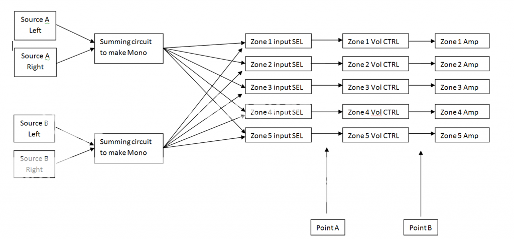 shows my initial concept.
One of the things that is necessary for the calibration process for the optocouplers is to run a dc signal through the audio signal side of the optcouplers so that it can be measured. I have two questions regarding that.
1. The original design used a relay network and a single channel ADC to switch between the optocouplers and record the current that passes through them at a given output from the DACs. Since I will be using 10 optocouplers rather than 4 I am thinking about just using 10 channels of ADC so that I do not have to switch between the optocouplers with hardware, and will do it in software instead. Does anyone see a pressing reason not to go that route?
2. It would obviously be bad to have DC voltage flowing through the summing circuit backwards or into the input of the amplifiers. I don't have the eagle files yet, but from what was posted in his thread on page 2 it looks like there are three relays per channel required to make the connections for testing purposes I think it should be possible to reduce this to a single DPDT if each optocoupler has it's own ADC. This occurs at Point B in my diagram. Because I plan to use a DPDT relay for the input selection rather than two single throw relays, I also need a way to keep the test signal from going back to the input (point A). Would it make sense to just use a diode to block that rather than adding another relay?
I think those are my two big questions for now, once I have some opinions about those issues I'm going to work on a true circuit diagram for a single channel of the opamp.
The project is frankly a rather ambitious one, particularly given my experience with electronics. I've built a couple of gainclones, and played with some other simple audio circuits but nothing this complicated. I'm very grateful for any advice, suggestions or points to consider, and if I question something it's because I want to understand it, not because I think I know better.
We've pm'd a little bit and they have graciously agreed to send me the eagle files for their project. There are several changes that will need to be made for my project, however, so I decided to start a new thread to build on their work.
The concept that I am working on is a gainclone amplifier for 5 zones/rooms that allows remote volume control. My initial thought was to use something that amounts to 5 mono "lightspeed attenuators" but I realized that buying 5 "matched pairs" of optocouplers was going to get expensive in a fast hurry, also I like the idea that the microcontroller can compensate for non-linearity in the optocouplers, even in a matched pair. I found oenboek's thread about their project and realized that there was the potential for improved linearity and some cost savings, albeit at the price of a lot more complication. Part of the cost savings comes from the fact that I should be able to get all of the ICs from TI for free through their sample program since I work at a University. It also has the advantage of paving the way for other mods like remote control of other aspects of the amplifier, soft start, etc.
Because the system is intended for whole house audio I do not think that having stereo is important, it will be a separate system from any home theater setup. I want to have two stereo inputs that each run into a summing circuit (probably an active summing circuit using an opamp) the two mono signals are then sent two five small dpdt latching relays so that each zone can choose between source A or B. Then each source goes through the attenuator stage and then off to the amplifiers which will probably be 5 lm3875s run from a single power supply. This flow chart
One of the things that is necessary for the calibration process for the optocouplers is to run a dc signal through the audio signal side of the optcouplers so that it can be measured. I have two questions regarding that.
1. The original design used a relay network and a single channel ADC to switch between the optocouplers and record the current that passes through them at a given output from the DACs. Since I will be using 10 optocouplers rather than 4 I am thinking about just using 10 channels of ADC so that I do not have to switch between the optocouplers with hardware, and will do it in software instead. Does anyone see a pressing reason not to go that route?
2. It would obviously be bad to have DC voltage flowing through the summing circuit backwards or into the input of the amplifiers. I don't have the eagle files yet, but from what was posted in his thread on page 2 it looks like there are three relays per channel required to make the connections for testing purposes I think it should be possible to reduce this to a single DPDT if each optocoupler has it's own ADC. This occurs at Point B in my diagram. Because I plan to use a DPDT relay for the input selection rather than two single throw relays, I also need a way to keep the test signal from going back to the input (point A). Would it make sense to just use a diode to block that rather than adding another relay?
I think those are my two big questions for now, once I have some opinions about those issues I'm going to work on a true circuit diagram for a single channel of the opamp.
The project is frankly a rather ambitious one, particularly given my experience with electronics. I've built a couple of gainclones, and played with some other simple audio circuits but nothing this complicated. I'm very grateful for any advice, suggestions or points to consider, and if I question something it's because I want to understand it, not because I think I know better.
I've got oenboek's eagle files so I'm going to have to spend some time with those. I need to figure out which DAC ADC pair will be best since I will need 10 channels of each, I'll probably use three 4 channel chips for a total of 12 since most of the larger channel count chips seem to be small, rather complex SMDs and there are some through hole 4 channel chips.
In the mean time I am working on the arduino code.
My current conundrum and the bulk of my code is here: Optocoupler-based volume control controlled with rotary encoder - Arduino Forum
In the mean time I am working on the arduino code.
My current conundrum and the bulk of my code is here: Optocoupler-based volume control controlled with rotary encoder - Arduino Forum
I couldn't find performant DACs or ADCs in through-hole at a reasonable price. But I also didn't want to take the challenge of soldering SMT. That's why I asked Tirna Electronics to buy and solder the SMT-parts on DIL-adapters for me. They do it at a very reasonable cost and the service is perfect.
Just my 2cents.
Joost
Just my 2cents.
Joost
What did you determine to be the performance requirements? Minimum 12 bit, is slew rate critical?
I wanted minimum 10bit in use. More is useless as the analog circuits can never reach that precision. 8 bit didn't feel OK to me (only 256 bits), especially in the low range, the precision needs to be high enough to keep Loudness steps small. I've chosen a 12-bit DAC as it was cheaper then a lower-bit one.
Slew rate is not important at all. The Sylonexs are very, very slow, so the measurements can be slow as well. I'm talking seconds before stabilizing ! A DAC/ADC needing 0.1 seconds for a measurement is more then fast enough.
Main criterium was cost, besides having at least 10 bits. You can pay fortunes for an ADC or a DAC. I tried to pay not more then a few euros.
- Status
- Not open for further replies.