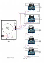
Is it possible to use a single unit PSU to power 5 individual chip amps this way? I'll like to have 5 individual units so I can power up any which one I wish to. Thanks.
Attachments
Last edited:
2A slow blow fuse probably won't last long when feeding a 500VA toroidal - the inrush current will eventually kill it. Suggest you uprate this to a 6.3AT.
If you're looking for the best sound, don't run the shield connection of the RCA inputs directly on to the pcb.
If you're looking for the best sound, don't run the shield connection of the RCA inputs directly on to the pcb.
2A slow blow fuse probably won't last long when feeding a 500VA toroidal - the inrush current will eventually kill it. Suggest you uprate this to a 6.3AT.
If you're looking for the best sound, don't run the shield connection of the RCA inputs directly on to the pcb.
Thank you. What is the alternate way to connect the RCA input then?
Have a look at this picture - its only for stereo but hopefully you'll get the idea and be able to apply it to your 5 channel set up. The key point is there's no direct wire from the RCA ins to the PCB - they go first to the chassis ground and only then on to the PCB from the central star point.
More grounding
More grounding
Hi. There isn't any gnd connection at the amp unit for my 5 channel. I did a pair of monoblocks without the pcb gnd connecting to the chassis gnd and there's no hum. When I connect the pcb gnd to the chassis's gnd, I get a hum.
Sounds like something's amiss elsewhere in the system then. The principle of taking the RCA shields straight to the star ground still applies, even if the star ground isn't connected to chassis.
Certainly you could try that - it might work. But you don't show the speaker ground return - is that another separate wire? Don't common the speaker ground with the RCA input ground unless you want an uncontrollable oscillator.
You mean to connect the speaker's gnd to the star gnd as well? Seems like a dangerous thing to do, would it? The spk gnd is from the pcb at the moment.
Ah, I see - what you have is fine. The speaker -ve terminal going to the PCB ground is fine. Seems in your situation with 5 channels, you have a star ground (on the PCB) for each channel. So maybe connecting the RCA ground to that isn't such a bad idea after all - ignore what I said earlier. I had imagined that your star ground was going to be in the PSU, but its not. I just wonder what happens when all 5 star grounds are connected together by the source component's ground... But just try it and see. Sorry for getting you more confused than you needed to be.
... I just wonder what happens when all 5 star grounds are connected together by the source component's ground... But just try it and see.
I wouldn't know either. will try and see whats the result.
First,
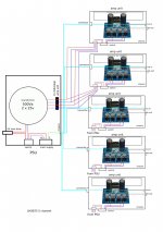
the post1 schematic shows mains powered equipment with exposed conductive parts NOT connected to Safety Earth. You must NOT build post1.
Secondly,
The Safety Earth that you have added is nothing to do with Audio Quality. It might make Audio Quality worse.
There is an exception to the do not build advice:
If you are capable of designing and building and TESTING, the completed PSU and can then guarantee that mains voltage will never contact any of the output wires, then the following equipment can be built without connection to Safety Earth.
As far as I know there is no advice in this Forum on how to do that design/build/test.
Finally,
the radiated magnetic field from AC cables is dependent on current. The Low Voltage AC connecting cables are a potential source of hum in any wire that acts as an aerial input to your chipamps.
The 2pair of AC wires running to each amplifier must be twisted as pairs and may benefit from an extra screen around the twisted pairs.
This screen could maybe comply with the Safety Earth connection that you should install. Adding a 5th core might be safer.
Last edited:
I do not see the problem that you see. Only the power transformer enclosure has AC line voltage, and I see a safety earth connection to that enclosure.First,
the post1 schematic shows mains powered equipment with exposed conductive parts NOT connected to Safety Earth. You must NOT build post1.
Secondly,
The Safety Earth that you have added is nothing to do with Audio Quality. It might make Audio Quality worse.
The output lines are low voltage and floating (transformer isolated). There is no safety earth connection required for anything connected only to the secondary side of the transformer. If you disagree, I would like to hear why.
The only reason that I would see an exception to my stance is if the transformer is hand made or even professionally custom wound. Then there has been no testing of the transformer to ensure electrical isolation between primary and secondary windings. A commercially purchased transformer can be assumed to be safe in that regard.
Around here (Canada), most or all Hi-Fi does not have a safety earth connection at all. They have two-prong electrical cords. It is the isolating property of the mains transformer that provides the necessary electrical safety.
it is the design, build and test that allows Class11 equipment to exist.the power transformer enclosure has AC line voltage, and I see a safety earth connection to that enclosure..............
.............most or all Hi-Fi does not have a safety earth connection at all. They have two-prong electrical cords. It is the isolating property of the mains transformer that provides the necessary electrical safety.
Unless you are trained in the whole of that process and have the necessary resources you cannot guarantee to meet the Class11 standard.
If you have mains electricity attached to a unit and then cable that unit to another remote unit, how can you guarantee that mains can NEVER, in all reasonable accident scenarios, pass to at least one of those many connecting wires in the 5 umbilicals?
If you electrically connect a power amp to a mains powered PSU then as far as I can understand, all the connected units must also comply with the "all exposed conductive parts must be connected to Safety Earth".
no, my previous comment applies.There is no safety earth connection required for anything connected only to the secondary side of the transformer.
as far as I know all mains transformers must pass a short term High Voltage test to ensure that primary to secondary isolation meets isolation specification. That isolation test has little or nothing to do with Class11 regulations. Isolation is a Class1 requirement.A commercially purchased transformer can be assumed to be safe in that regard.
First,
the post1 schematic shows mains powered equipment with exposed conductive parts NOT connected to Safety Earth. You must NOT build post1.
There is an exception to the do not build advice:
If you are capable of designing and building and TESTING, the completed PSU and can then guarantee that mains voltage will never contact any of the output wires, then the following equipment can be built without connection to Safety Earth.
As far as I know there is no advice in this Forum on how to do that design/build/test.
Finally,
the radiated magnetic field from AC cables is dependent on current. The Low Voltage AC connecting cables are a potential source of hum in any wire that acts as an aerial input to your chipamps.
The 2pair of AC wires running to each amplifier must be twisted as pairs and may benefit from an extra screen around the twisted pairs.
This screen could maybe comply with the Safety Earth connection that you should install. Adding a 5th core might be safer.
Thanks. It is a separated PSU, only that it is powering 5 individual amps. If it is too dangerous then I'll look at other alternate ways.
"....Left of the vertically standing units is a powersupply with a 500VA 25 0 25 toroidal, with 40000uF per rail supplying +-35V to 5 x lm3886 chipamps. Each of the vertical units contains one lm3886 chipamp running the 5 channels of my sound system...." POST# #355http://www.diyaudio.com/forums/solid-state/168482-ksa50-amp-new-production-live-36.html
I got the idea from this guy "tangmonster".
I got the idea from this guy "tangmonster".
Attachments
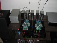
IN the power supply enclosure GND is earthed.
The plugs i used is standard 3 pin nutrix "microphone" plugs
They have 3 pins for +35 gnd -35 and a 4th "shield" pin
So All 5 of the plugs has got a 4 core cable with earth connected back to main power supply enclosure. to make sure each metal box is connected to main earth in power supply.
I did not connect my GND in the small boxes to the individual earth in each small box.
I do not have a switch for the small boxes if the power supply is switched on everything comes on. They use very little power if no signal is fed
In short. Having everything in one box might be simpler , but i really like the look ,and they have been working fine for the last few years 🙂
The heat sinks for the lm886 chips are 150x 50 x 50 which is nice and overkill for one lm3886 chip driving 8 ohm speakers.
PS
I saw took this idea from user "okapi". if you browse through the photo gallery of chipamps you'll find his crazy build with 4 separate power supplies.
Last edited:
- Status
- Not open for further replies.
- Home
- Amplifiers
- Chip Amps
- 5 channel chip amps