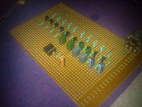
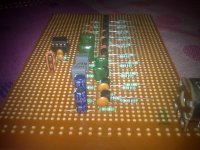
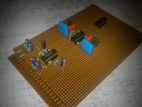
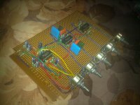
I modded a 10 band eq circuit by omitting 5 bands to make a 5 band equalizer.
But, it didn't worked. Hum on both channels, no audio, checked the circuit and the connections several times, no errors, no mistakes, no shorts.
Kindly help, or i would start over again with a new circuit if anyone could share.
Regards,
Aniket
But, it didn't worked. Hum on both channels, no audio, checked the circuit and the connections several times, no errors, no mistakes, no shorts.
Kindly help, or i would start over again with a new circuit if anyone could share.
Regards,
Aniket
Attachments
Hi Aniket,
Sorry to hear that your board is not working as expected.
How did you make the power supply ? It's a dual power supply as I guessed it from your post.
Could you post your modded Power supply Section circuitry of this Eq ?
I have made a 3 band Eq following the circuit from this page below. It has a 5 band and 10 band circuits too. Their performance is really very good and simple to build as well , as I personally found.
Sam Electronic Circuits
Last edited:
Hi csom,
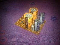
I made the psu myself, yes its a dual power supply
Its simple with a 12-0-12 V sec. transf. and bridge made using 1N4007 diodes, 10R 1W resistors and 2200uF filter caps.
Have you made this 5 band eq. using transistors as shown in the link you mentioned. //http://users.otenet.gr/~%20athsam/EQ_3.htm
Regards,
Aniket
Attachments
Hi csom,
I made the psu myself, yes its a dual power supply
Its simple with a 12-0-12 V sec. transf. and bridge made using 1N4007 diodes, 10R 1W resistors and 2200uF filter caps.
Have you made this 5 band eq. using transistors as shown in the link you mentioned. //http://users.otenet.gr/~%20athsam/EQ_3.htm
Regards,
Aniket
If you are getting the desired voltages at the collectors of the transistors and the pins of the line driver opamp TLO72, then it might be a ground issue as per the symptoms you stated earlier.
Also make sure your signal is being fed correctly to the circuit and it has a proper ground connection.
If any input or output capacitor is open, then the circuit might not respond.
Also make sure the dual pots are properly soldered. Sadly I found 3 bad pots with a manufacturing defect. But that's a very rare case.
I would prefer LM317 and LM337 for the dual power supply section.
I have only built the 3 band Eq section from that site and I'm really very happy with it.
But next I'll try the 6 band one as I really love opamps over transistors, a purely personal preference.
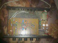
made all the connections correctly, used shielded wires for both input and output signals, hum present on both channels, no audio with input connected to PC and output to amp.
I checked all the connections circuit several times, found no mistake according to the schematic.
Replaced TL072 with NE5532 and NJM4558 but same result, also i must tell that i used BC547 instead of 2SC1740, but both are almost identical GP transistors and all caps are fine.
'might be a ground issue' please elaborate Dear Som, i coudnt understand.
At last i removed the board from the chasis and placed my same old 5 band eq board i made 4 yrs. ago using 2 transistors per channel, still working nice.
Regards,
Aniket
Did you check if the voltages are correct at the collector, base and emitter of the transistors ?
Please have a look here.
http://www.diyaudio.com/forums/anal...3-band-graphic-equalizer-sos.html#post3284188
.......
'might be a ground issue' please elaborate Dear Som, i coudnt understand.
Please have a look here.
http://www.diyaudio.com/forums/anal...3-band-graphic-equalizer-sos.html#post3284188
Most 2SA/B/C/D transistors has its collector at the central pin, BC's in place, has the base. Did you check it?
i have gone through your whole thread Som,
there's no ground issue on my board, and voltages are fine across all transistor pins.
and i have made it on a general purpose PCB, as i said earlier no mistakes according to the schematic, and I checked transistor pins while soldering.
I have some TL072, TL074 and NE5532 opamps,
anyone could advice me a nice and working 5 band eq circuit.
Regards,
Aniket🙂
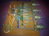
First of all, solder a wire on the metal sheet of all the potentiometers and connect it to the ground point on the filter capacitor.
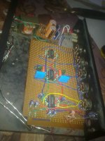
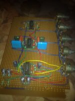
Next, u have very long wires. So better make all things as small as possible. Those green and other wires r also too long.
As Oswaldo suggested, check the transistors with a fresh mind.
Gajanan Phadte
Next, u have very long wires. So better make all things as small as possible. Those green and other wires r also too long.
As Oswaldo suggested, check the transistors with a fresh mind.
Gajanan Phadte
Last edited:
I dropped that project and kept that board aside for a while, would check that later.
As i need the eq. urgently, i am constructing another circuit, as attached using TL074 opamps. I found the schematic on HiFiEngine, would update soon.
Hi, Gajanan, thanks a lot for the advice, as the chasis is grounded, no need to ground the potentiometers, hum is not present due to any grounding mistake,
maybe the schematic is wrong and need to rectify that.
As of now, I'm uploading both the schematics, advice is most welcome.
Regards,
Aniket
Attachments

1. Can you try your earlier 5 band Equalizer circuit with a circuit simulator like LTSpice etc. so that you might get what's going wrong with your mod?
2. How about using a project board/bread board like the following instead of the vero board/perf board at first to test, you could save money I guess. Just a suggestion.
http://www.diyaudio.com/forums/atta...phic-equalizer-sos-graphic-eq-bread-board.jpg
2. How about using a project board/bread board like the following instead of the vero board/perf board at first to test, you could save money I guess. Just a suggestion.
http://www.diyaudio.com/forums/atta...phic-equalizer-sos-graphic-eq-bread-board.jpg
Last edited:
Hi Som,
Yes, i would LTSpice my earlier mod sometime later for sure. vero board are really cheap here in Delhi and Gurgaon, cost only 25 Rs. I have never used bread board, and may be the are expensive here. I am good at soldering i find it easy to construct on a vero board.
Regards,
Aniket
Yes, i would LTSpice my earlier mod sometime later for sure. vero board are really cheap here in Delhi and Gurgaon, cost only 25 Rs. I have never used bread board, and may be the are expensive here. I am good at soldering i find it easy to construct on a vero board.
Regards,
Aniket
I am eager to know about your progress and the result with this ongoing 5 band Eq project.
Please do keep us informed about your "YAY!". 🙂
Wish you all the very best.
Thank you.
Please do keep us informed about your "YAY!". 🙂
Wish you all the very best.
Thank you.
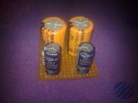
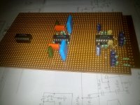
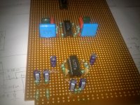
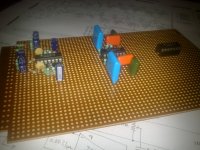
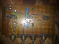
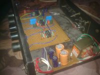
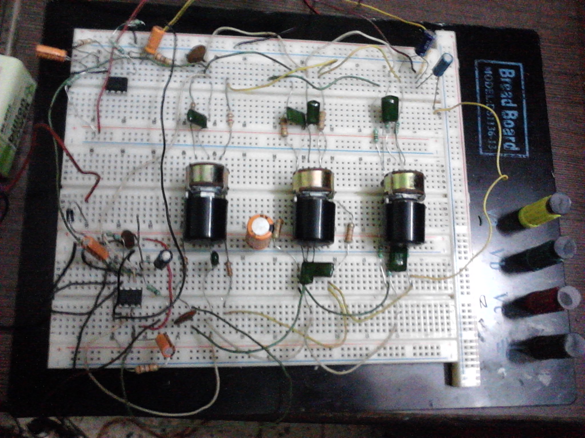
New eq. working great, nice control on each frequency band, no hum, hiss, dead quiet, crystal clear sound. Here are a few pics. I would also mention that I changed value of C10 to 0.01uF instead of 0.001uF as in the schematic for 13kHz frequency band, with 0.001uF there was no cut or boost, but working brilliant with 0.01uF.
Regards,
Aniket
Regards,
Aniket
Attachments
Hi Aniket,
I want to make an equalizer using some left over TLO74s. But I found that some parts are illegible in your uploaded reference. Could you kindly post your modded, simplified and tested circuit so that I can follow it?
Eagerly awaiting your reply.
Thank you. 🙂
I want to make an equalizer using some left over TLO74s. But I found that some parts are illegible in your uploaded reference. Could you kindly post your modded, simplified and tested circuit so that I can follow it?
Eagerly awaiting your reply.
Thank you. 🙂
Hi csom,
please tell, how many bands you require??
the circuit which I am currently using is a 5 band eq. using all TL074's. and it's working great.
how many frequency bands you require, please elaborate your needs, i will help.
Regards,
Aniket
please tell, how many bands you require??
the circuit which I am currently using is a 5 band eq. using all TL074's. and it's working great.
how many frequency bands you require, please elaborate your needs, i will help.
Regards,
Aniket
Hi Aniket 🙂
I need a 5 band eq to fix an old amp. So it would be great if you could give me a 5 band using TLO74 since I have some unused TLO74 chips with me.
Thank you so much 🙂
I need a 5 band eq to fix an old amp. So it would be great if you could give me a 5 band using TLO74 since I have some unused TLO74 chips with me.
Thank you so much 🙂
- Status
- Not open for further replies.
- Home
- Source & Line
- Analog Line Level
- 5 band equalizer, need help!!