Attachments
Last edited:
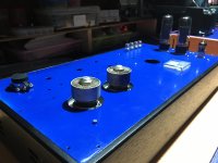
That looks very nice!
Can you see the light from the filament through the glass envelope that is between the screen connection ring, and the outer plate structure?
Please post a schematic.
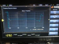
What circuit topology, or what output transformer, is giving that 5.5 dB of high frequency peaking?
Of course, that peaking will not effect the signal output of a CD player that has the brick wall output filter (44.1kHz / 2 = 22.05kHz).
Can you see the light from the filament through the glass envelope that is between the screen connection ring, and the outer plate structure?
Please post a schematic.
What circuit topology, or what output transformer, is giving that 5.5 dB of high frequency peaking?
Of course, that peaking will not effect the signal output of a CD player that has the brick wall output filter (44.1kHz / 2 = 22.05kHz).
Last edited:
Not wishing to be harsh but just posting a few pictures and audio clips doesn't really tell us much. I can see you've put a lot of work into these amps but listened to the first video clip, there was distortion on the bass notes; what thd figures do you get?
External anode RF power tubes?
What plate voltage are you running, these usually like a kV or so?
Also a note on external anode ceramic tubes, the pin seal temperature is critical if pushing any real power, and you will probably want to be using air system sockets and chimneys with considerable air pressure to keep the seal temperature down.
These are indirectly heated oxide cathode tubes and you really want the heaters on a few minutes before applying HT for best life and the avoidance of cathode poisoning.
Finally, watch the grid current, blowing out the grid is a notorious failure mode on these, main grid is only good to 2W, and the screen grid dissipation tops out at 12W or so if I recall.
External anode RF power tubes?
What plate voltage are you running, these usually like a kV or so?
Also a note on external anode ceramic tubes, the pin seal temperature is critical if pushing any real power, and you will probably want to be using air system sockets and chimneys with considerable air pressure to keep the seal temperature down.
These are indirectly heated oxide cathode tubes and you really want the heaters on a few minutes before applying HT for best life and the avoidance of cathode poisoning.
Finally, watch the grid current, blowing out the grid is a notorious failure mode on these, main grid is only good to 2W, and the screen grid dissipation tops out at 12W or so if I recall.
It looks like the OP may be using air system sockets, though they aren't terribly effective without chimneys.
What's more concerning, however, is that there doesn't seem to be a top cover to these, so there is potentially somewhere in the neighborhood of 1200 V (just a guess, not sure what the OP is running) exposed on the chassis. That's fine for a test jig, but for an amp that you're actually going to use, that's asking for someone to get hurt or killed.
Why is the frequency response so horrible? What's going on here? The YouTube clip sounds very distorted.
Jan
A youtube clip is only as good as the microphone or sampling device, right? That's why I never bother with youtube clips of amplifiers.
It looks like the OP may be using air system sockets, though they aren't terribly effective without chimneys.
What's more concerning, however, is that there doesn't seem to be a top cover to these, so there is potentially somewhere in the neighborhood of 1200 V (just a guess, not sure what the OP is running) exposed on the chassis. That's fine for a test jig, but for an amp that you're actually going to use, that's asking for someone to get hurt or killed.
In the video, it looks like there are glass chimneys around the anodes, which will help with the airflow, assuming that there's an adequate blower pushing air. But AGREED about the need to shield bystanders from B+ at the potential levels involved - this is not ouch territory, this could be RIP territory.
Standard 4X150s are originally glass envelope external anode tubes, not ceramic. The 4cx250 was its design successor that went with the ceramic (as indicated by the "cx"). Though there are probably 4x150s floating around that are ceramic- you can nearly always use a 4cx250 in a circuit designed for a 4x150 (but not vice versa) and at some point some manufacturers may have just made all-4cx250s, but labeled some of the 250s as 150s, for simplicity of production.
The x150 and x250 have a wide reputation for really poor distortion characteristics, at least when operated in their intended tetrode mode, in RF applications for which they were designed (and in which distortion tends to be less of a major focus than audio), except in configurations with very considerable negative feedback. I looked into these tubes quite a bit some years ago because at one point was I was very intrigued at the idea of a tube this small with this much dissipation, high gain, and relatively small filament current demands; the more I learned, the more I lost interest. Not sure about whether they can be run effectively in triode mode (their screens are infamously frail) or how they behave in triode mode. And perhaps they behave better in single-ended Class A.
I am _not_ trying to demean the original poster or his/her work -this looks like an ingenious, fun, and overall well-done project - just some info for others who may be considering the x150 or x250 series tubes. I'd be very interested in knowing if the tubes perform well in single-ended Class A.
Last edited:
Anyone have triode curves for the 4X150?
I have too many sitting in my junk collection waiting for use.
I have too many sitting in my junk collection waiting for use.

I was able to get some triode curves for the 4x150.
Looks fairly good. Note this was done with one sample tube with variable power supplies and volt/ammeters. Some measurement errors may exist.
Next thing I need to do is measure screen current especially at higher voltages.
Will let me know how much plate voltage this tube would tolerate.
Since this is a tetrode it may handle higher voltages gracefully for ultralinear use.
One note is you need to be sure the plate connection does not detach when using as a triode. The screen current will spike and the tube will likely die.
These things will work beautifully in UL BUT do not try to the typical silliness of tapping the primary. You need a separate screen winding with the screen at 350V and about a KV on the plate. Figure about 30% feedback, watch what the screen/anode voltage ratio looks like and you'll see a winner. The matter is cooling, which I solved 25 years ago https://www.pearl-hifi.com/06_Lit_Archive/07_Misc_Downloads/RB300_3CX_Data_Sheet.pdf. d'load all this for the skinny on UL https://www.pearl-hifi.com/06_Lit_Archive/02_PEARL_Arch/Vol_01/Sec_02/070_Vol_01_Sec_02_Comp.pdf and dig up Rudolph Moers last article in Jan Didden's Linear Audio https://linearaudio.net/
- Home
- Amplifiers
- Tubes / Valves
- 4x150a. Single end. Test