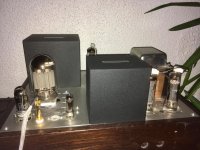
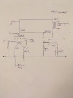
I buildt a 13e1se amp 7 years ago. IDH Pentode driver with unbypassed cathoderesistor, shunt feedback from plate of output tube. A simple schematic
drawing attached.
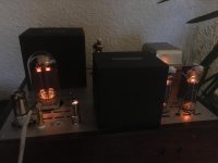
Also two pics of one monoblock after mocking up 4p1l .
I have altered the original amp several times. It was buildt with Lundahl opt First, got custom sowter irons after a year, and Monolith custom choke and Opt
A few years ago. The driver tube was first 12gn7a, It was replaced by e282f
Which resulted in lower thd. With the ll opt output at clipping was about 32w
As the Monolith opt has a higher reflected load output is just above 20 W
I intend to change psu and up the power at clipping.
So I did not have any second thoughts about abusing the top plate with some
Holes. The last years my main interest has been dht's.
So let's check the 4p1l as pentode driver.
The schematic shows the starting point. Suggestions for improvements are very welcome.
Ps : Ale I had forgot that pout was lower with the Monolith opt. The 4p1l is not resulting in preliminary clipping
drawing attached.
Also two pics of one monoblock after mocking up 4p1l .
I have altered the original amp several times. It was buildt with Lundahl opt First, got custom sowter irons after a year, and Monolith custom choke and Opt
A few years ago. The driver tube was first 12gn7a, It was replaced by e282f
Which resulted in lower thd. With the ll opt output at clipping was about 32w
As the Monolith opt has a higher reflected load output is just above 20 W
I intend to change psu and up the power at clipping.
So I did not have any second thoughts about abusing the top plate with some
Holes. The last years my main interest has been dht's.
So let's check the 4p1l as pentode driver.
The schematic shows the starting point. Suggestions for improvements are very welcome.
Ps : Ale I had forgot that pout was lower with the Monolith opt. The 4p1l is not resulting in preliminary clipping
Attachments
Last edited:
Do you like the sound? How does it compare to the E282F?
Always so good looking builds, great work!
Always so good looking builds, great work!

When I used the 4P1L in pentode I found that the distortion could be minimized when screen voltage can be reduced from 150V to 80V.
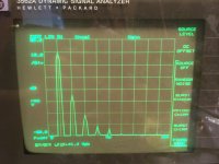
Here is a test, the gain is far too much (43dB / 147x) due to the gain set resistor. However, it shows it can deliver 200Vpp at less than 0.3% with H2 at -67dB and H3 at -52dB.
http://www.bartola.co.uk/valves/2013/01/12/4p1l-pentode-driver-test-2/
It can do as well and better than the E282F 🙂
Second question will be which one you prefer sonically once you optimise the driver 🙂
Cheers
Ale
So far I have never looked back after implementing
Direct heated tubes��
Your posts about the 4p1l as pentode driver
Inspired me to start this try out : your website and contributions to diy'ers are of great value
I will replace the 150 V vr with a 107v/75v
Actually , I found the lowest g2 voltage giving sufficient conduction also resulted in lowest thd when I meassured the 13e1 many years ago.
Thank you Vegard! I did the tests with a MOSFET follower driving G2 from a pot divider setting the screen voltage. I adjusted the screen voltage accordingly to minimize distortion at maximum swing (200Vpp) and found that 80-90V was best
Keep us posted on your progress and listening impressions! I bet the 13e1 SE sounds amazing!
Cheers
Ale
Keep us posted on your progress and listening impressions! I bet the 13e1 SE sounds amazing!
Cheers
Ale
Thread resurrection...
I've been thinking about using a 4P1L in pentode mode to drive a 300B, sort of like a WE91 but with a directly heated pentode as the driver tube.
Anyone tried this?
I've been thinking about using a 4P1L in pentode mode to drive a 300B, sort of like a WE91 but with a directly heated pentode as the driver tube.
Anyone tried this?
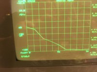
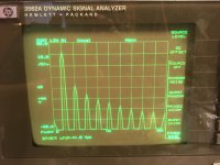
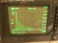
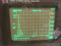
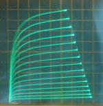
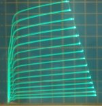
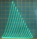
4P1L pentode curves can be squared up with +15V (wrt cathode) on grid 3. May lower distortion.
Curves:
a) 4P1L 0V on grid3, +81V on grid 2
b) 4P1L +15V on grid3, +81V on grid2
c) 4P1L in triode mode
Curves:
a) 4P1L 0V on grid3, +81V on grid 2
b) 4P1L +15V on grid3, +81V on grid2
c) 4P1L in triode mode
Attachments
Last edited:
- Home
- Amplifiers
- Tubes / Valves
- 4p1l pentode driver