I'm confused about the proper filament supply design for the 4P1L, or any DH tube, I suppose.
I've seen PSE schematics that show each channel (2 tubes) being heated by the same filament supply.
Yet, I've read posts elsewhere that claim that DH tubes always need to be heated using a separate filament supply for each individual tube, regardless of whether the topology is SE, PSE, PP or PPP.
Which is correct and does it apply under all circumstances? In other words:
Do different topologies (SE, PSE, PP, PPP) affect what is allowable?
Do different bias schemes (cathode, fixed, filament) affect what is allowable?
You just can't heat right and left channel tubes from the same supply.
Think of your supply as being part of the cathode circuit. If you run right and left channel tubes off a single supply, it would be as if you tied the cathodes together.
But in circuits where you intentionally tie tube cathodes together such as a PSE or a PP amp, you can get away with a single supply per channel.
Yes, separate supplies per tube. With the 4P1L think of filament bias - a lot of users use filament bias because it eliminates the cathode bypass. You need Rod Coleman regulators from Lyrima. He can explain everything including values and circuit. This applies to other tubes like 26, 10Y. Not to 2a3, 300b or 45 since grid voltage is too high for filament bias. You can still use Rod's regs for any DHT.
OK . . . I see the same disagreement exists here.
Andy, what's the problem with just heating each channel separately, as Tjj suggests?
If I use these (however I heat them) I'm leaning toward fixed bias using a Lithium battery. This also eliminates the need for a cathode bypass cap. It also doesn't require high wattage resistors that generate excess heat and, I believe, it also allows for the use of a lower B+.
But my main concern right now is how to heat them.
You just can't heat right and left channel tubes from the same supply.
Think of your supply as being part of the cathode circuit. If you run right and left channel tubes off a single supply, it would be as if you tied the cathodes together.
But in circuits where you intentionally tie tube cathodes together such as a PSE or a PP amp, you can get away with a single supply per channel.
Why not, if cathodes are tied to common channel ground (fixed bias)? And have LC decoupling (inductor between each filament, or CCS)?
Sharing a filament supply with DHT/Ps s possible - you will just be mixing the signal of the shared tubes. So not a great idea for stereo channels - but sharing will not damage the tubes as long as each filament sees the correct voltage and current.
@50AE
Yeah I have certainly thought about that before. With fixed bias it might work. But with cathode bias, I think you will have issues.
But who knows. Maybe there is something I am not considering. Like the OP I have always been told 1 supply per tube unless certain conditions are met.
Yeah I have certainly thought about that before. With fixed bias it might work. But with cathode bias, I think you will have issues.
But who knows. Maybe there is something I am not considering. Like the OP I have always been told 1 supply per tube unless certain conditions are met.
Hi - sorry I misread the initial post. Yes, in PSE I heat each pair of tubes from the same supply, since they are in parallel.
You can put a 1 ohm resistor between each tube plate and the OPT to check for idle current balance. It certainly would be a nice idea to use well matched tubes. When sharing a filament supply and cathode bias resistor, if one tube peters out, the remaining tube will shoulder quite a burden electrically.
So, it seems to definitely be OK to heat two tubes in a single channel with the same supply. I assume this applies to either PP or PSE. Correct?
To be more specific, I'm building a PP amp with fixed bias.
But @50AE seems to be suggesting that it would be OK to heat both channels with a single filament supply, just as you would with indirectly heated tubes, if the following conditions apply:
A) fixed bias is used with all cathodes grounded
AND
B) if each channel is decoupled separately from the supply?
You suggested LC but what about RC decoupling?
I want to use a Meanwell AC-DC, switch mode, 3.3v 3A, supply and I planned on adding an RC section to drop voltage to 2v and wire the tubes in parallel. Alternatively, the output voltage is adjustable up to 3.6v so I could run the filaments in series at a slightly starved voltage.
I have a pair of them but if I can get away with using only one without it affecting stereo separation, it would save space.
This is the supply: Blocked
Not sure if that link works . . . here's the data sheet:
https://www.meanwell.com/Upload/PDF/RS-15/RS-15-SPEC.PDF
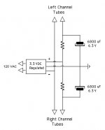
It has connections for +, -, and ground. Can it be hooked up like this?
To be more specific, I'm building a PP amp with fixed bias.
But @50AE seems to be suggesting that it would be OK to heat both channels with a single filament supply, just as you would with indirectly heated tubes, if the following conditions apply:
A) fixed bias is used with all cathodes grounded
AND
B) if each channel is decoupled separately from the supply?
You suggested LC but what about RC decoupling?
I want to use a Meanwell AC-DC, switch mode, 3.3v 3A, supply and I planned on adding an RC section to drop voltage to 2v and wire the tubes in parallel. Alternatively, the output voltage is adjustable up to 3.6v so I could run the filaments in series at a slightly starved voltage.
I have a pair of them but if I can get away with using only one without it affecting stereo separation, it would save space.
This is the supply: Blocked
Not sure if that link works . . . here's the data sheet:
https://www.meanwell.com/Upload/PDF/RS-15/RS-15-SPEC.PDF
It has connections for +, -, and ground. Can it be hooked up like this?
Attachments

Last edited:
No, if bias is cathode "auto", or you will get some "stereo base expansion". Yes, if cathodes are grounded. For 4P1L better connect halves of the filament in parallel.
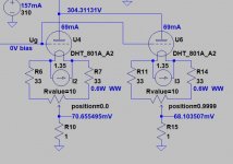
I'm not a fan to use DHT tubes with common heater supply.
The balancing of tubes (equal static anode current at selected operating point) almost impossible.
Different /hot/ filament resistances results different filament currents, which may occurs small -but measurable- operating point slipping. In the case of low filament voltage DHT is even tolerable, but not in case of large transmitting tubes.
The correct solution is using separated filament PSUs, and individual "hum balancing", which allows minimal operating point correction too.
See the sample:
Attachments
@Wavebourn
So, do I understand correctly that you agree with @50AE that I could use one supply for both channels if I use fixed bias?
And would the schematic I posted work with the Positive from the Meanwell supply going to to pins 1 and 7, and the Negative from the supply going to Pin 8, the center tap?
Is there some reason why parallel is better?
@euro21
The 4P2L is only 2.1v in parallel and 4.2v in series so that should not be a big problem.
I have a dozen of these and I'll add a resistor to each plate so I can check the current. Supposedly, they are very consistent tubes so I should be able to find 4 that are fairly close.
Last edited:
Yes, it will work. And if to compare 4.2V difference between different parts of the cathode to -10V bias, it is quite significant, is not it? 2.1 would lead to more uniform result across the cathode-grid. You can view each gap between grid wires as a separate triode, many in parallel. They should be matched as best as possible, right?
One more question, the data sheet says G3 should be at 0 volts. Does that mean it should be grounded? It seems I've heard that it should be connected to one of the other elements.
I want to try these in both pentode and triode. Would the G3 connection be the same for pentode and triode?
I want to try these in both pentode and triode. Would the G3 connection be the same for pentode and triode?
I'm not a fan to use DHT tubes with common heater supply.
The balancing of tubes (equal static anode current at selected operating point) almost impossible.
Different /hot/ filament resistances results different filament currents, which may occurs small -but measurable- operating point slipping. In the case of low filament voltage DHT is even tolerable, but not in case of large transmitting tubes.
The correct solution is using separated filament PSUs, and individual "hum balancing", which allows minimal operating point correction too.
See the sample:
Euro21 is correct: parallel-connecting DHT filaments will not give good results, if you care about performance.
With Push-pull circuits, the anode-currents in each filament are in anti-phase, so connecting the filaments together directly produces a local conflict.
However, if grid bias is used, or a shared cathode resistor (so that the "cathode" voltage is exactly the same for both DHTs) the unregulated voltage can be shared. So you can use a single transformer/rectifier to generate the raw DC voltage, and use two separate filament regulators. The regulators isolate the anode-currents from each other, and all is good.
One more question, the data sheet says G3 should be at 0 volts. Does that mean it should be grounded? It seems I've heard that it should be connected to one of the other elements.
I want to try these in both pentode and triode. Would the G3 connection be the same for pentode and triode?
Connect G3 to the cathode in pentode mode. In triode mode connect G2 and G3 to anode.
I did not try it in pentode mode, but in triode mode it can give 2.5W power in A2 mode, instead of 1.8W in A1. Up to +12V swing on G1.
Here was my thread: One more 4P1L SE
Last edited:
Are you saying that I should not connect the filaments in parallel under any circumstances, due to concerns about anti-phase conflict?Euro21 is correct: parallel-connecting DHT filaments will not give good results, if you care about performance.
With Push-pull circuits, the anode-currents in each filament are in anti-phase, so connecting the filaments together directly produces a local conflict.
However, if grid bias is used, or a shared cathode resistor (so that the "cathode" voltage is exactly the same for both DHTs) the unregulated voltage can be shared. So you can use a single transformer/rectifier to generate the raw DC voltage, and use two separate filament regulators. The regulators isolate the anode-currents from each other, and all is good.
Or . . . are you saying ("However") that if I use "grid bias" (fixed bias, negative voltage applied to grid) or a shared cathode resistor, that parallel filaments pose no problem?
And . . . are you saying that, if I use fixed bias, I can use a single filament supply to heat both channels (all 4 tubes in PP) or that a single supply should be used for each channel (2 PP tubes each)?
@Wavebourn has suggested that a single supply can be used for both channels since I will be using fixed bias, and that parallel filaments are preferable. Hence my continued confusion.
You also suggest using an unregulated supply and then isolating the anode currents from each other by adding "two separate filament regulators". Again, do you mean a separate regulator for each tube or one for each channel.
I'm planning on using the Meanwell AC-DC 3.3v 3A switch mode supplies I linked earlier. The data sheet seems to indicate that they are already internally regulated (Load Regulation +/- 2%) .
https://www.meanwell.com/Upload/PDF/RS-15/RS-15-SPEC.PDF
If I run parallel I will need to drop the voltage down to 2.1v using an additional RC section. I've posted a proposed schematic showing a single supply heating both channels with a separate RC section feeding each channel. Will this also serve to isolate the anode currents from each other?
Attachments
Last edited:
Hopefully @Rod Coleman will respond. But comments from others are also welcomed, of course.
My confusion stems from his use of the word "However" which, to me, indicates that there is an "exception to the rule", so to speak.
Reading his comments again, I'm guessing that he is suggesting a solution to the issue of "anti-phase conflict", which he claims results from using parallel heating. That solution is to use an unregulated supply and then add separate regulators, which will allow parallel heating.
Is my interpretation correct? Still, I'm not sure if he means a separate regulator for each channel or one for each tube?
But my Meanwell supply is already regulated. Will the schematic I posted also solve the issue of "anti-phase conflict"?
Regarding the choice between parallel and series heating and the issue of "anti-phase conflict" . . .
@Wavebourn has suggested that parallel (2.1v) would be better because it's preferable to minimize the voltage difference between the filament and the bias voltage.
@Rod Coleman . . . apparently disagrees, saying that filaments in parallel results in anti-phase conflict between the two tubes in a PP circuit. Presumably, he thinks series heating is preferable because it eliminates the anti-phase issue.
Would the following arrangement satisfy the concerns of both of you?
The 4P1L has three filament pins (1, 7 and 8) with pin 8 being the center tap. Would it be possible to eliminate this anti-phase conflict by connecting tube #1 with the Positive of the supply to pins 1 and 7 and the Negative to pin 8, and then on tube #2, connecting the Positive to pin 8 and the Negative to pins 1 and 7?
Would such an arrangement effectively run the filaments in series (thus eliminating the anti-phase issue) and also allow the use of 2.1v instead of 4.2v?
Would this even work??
- Home
- Amplifiers
- Tubes / Valves
- 4P1L Filament Supply Confusion