hi,
i'm looking for a clock to build an oversampling dac.
I need 49.152mhz
i want low-cost and good-performance clock, so i'm looking for a pll or something like this.
The clock must work with 3.3v power supply (because all others chips i use are 3.3v)
i found the ics848-05c clock multiplier. It claims 25ps jitter and work with only a 2.048mhz clock.
it is good ?
do you know something better ?
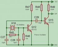
Below is a 49.152MHz “Pierce” XO. If operated from a Very Low Noise PSU it will give sub 10pS Phase Noise Performance. It can be operated from 3V3 - you might have to tweak the component values, details below: -
It uses a trick I’ve only just come across – but apparently its commonly known. By reducing the value of the resistor across the Crystal in a Pierce oscillator, from the typical 1M to a value between 3K3 to 10K you force the Crystal to resonate at its third overtone.
C28 - Could be replaced with a variable Capacitor say 4-20pF to trim Frequency
C27 – Value dependent on Crystal – watch Mark-Space ratio and Frequency
Q12, Q13 MPSH10, BFS17 etc
If you find that the output oscillates at 16.384 (the Crystals fundamental) then try changing the value of R45 from somewhere between 3K3 to 10K.
Operate the XO from a clean supply – PSU decoupling not shown – use 100nF ceramics across power rails.
Attachments
hi,
i built that on a test board and i have some problems.
transistors used are bsx20 (should be equivalent)
the first part of the schematic (xtal, and first transistor) works well (i thought).
i can see a sinus at about 50Mhz (i can't mesurate it accurately) with some dc. (should be normal)
when i connect the 56pF capacitor and the second part of the schematic, the output at collector of the first transistor isn't sinus at all and at output, i have a ugly signal and the frequency isn't good anymore.
can i do something to improve ??
if i replace the second stage by a comparator, like ad8561, would it be better ?
thanks
Sorry! 
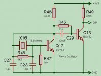
After rechecking my circuit, pls. note the correct position for R45.
After checking circuit operation @ 3V3 I also changed C29 to 100pF.
With the transistors shown, the duty cycle is 48% - which is not bad, Rise and Fall times of 2nS, could be improved with a higher fT transistor for Q13, such as a BFS17.
The corrected circuit (note position of R45), for improved performance Q13 should be replaced with a BFS17. For 3V3 operation R49 could be reduced to say 240R for improved Rise times.
Attachments
hi,
i made your modifications and that's not good yet.
on the output, i have a beautiful sinus signal with about 0.8v dc and 0.5v amplitude.
the frequency seems to be correct (about 20ns period)
the circuit is operating on 5vdc for testing.
i made your modifications and that's not good yet.
on the output, i have a beautiful sinus signal with about 0.8v dc and 0.5v amplitude.
the frequency seems to be correct (about 20ns period)
the circuit is operating on 5vdc for testing.
The Circuit is good, I have it working on the bench, try changing the transitor Q13 to a higher fT type.
Hi Apolon34,
maybe you have problems with your scope bandwidth or probe capacitance or compensation? You neeed 150 Mhz bandwidth scope&probe to see anything resembling 50 MHz square wave and 500MHz to measure it properly.
Best regards, Jaka Racman
maybe you have problems with your scope bandwidth or probe capacitance or compensation? You neeed 150 Mhz bandwidth scope&probe to see anything resembling 50 MHz square wave and 500MHz to measure it properly.
Best regards, Jaka Racman
hi,
i have a 60mhz scope and probe.
scope have input impedance of 1M ohm // 15pF
the probe is ok with the square signal test of the scope.
i don't see a square, but a perfect sinus wave and the amplitude isn't ok (about 1.5v p-p) and about 1.6v dc
seems like if q13 hfe is too low to saturate the transistor.
i measured it about 80
maybe that's the base resistor value that is bad (1.5k) ?
oh sorry,
i was using my probe in 1x mode.
in 10x mode, there's a small dc component (arround 0.2v) and the signal isn't sinus anymore. it's like a distorted square, but that might be the fault of the probe/scope.
i'll try to test that with a better scope/probe at my job
thanks for all
i was using my probe in 1x mode.
in 10x mode, there's a small dc component (arround 0.2v) and the signal isn't sinus anymore. it's like a distorted square, but that might be the fault of the probe/scope.
i'll try to test that with a better scope/probe at my job
thanks for all
The Tops & Bottoms of the "Square Wave" are not as clean as I would like, but the critcial edges between 1.5V and 3.5V are clean and fast, insuring good logic transistions with Low Phase noise - no hanging around in an undefined logic state!
A faster transistor for Q13 could help - and circuit values are not absolute! - just ones that work will with the transistors and layout I use 🙂
A faster transistor for Q13 could help - and circuit values are not absolute! - just ones that work will with the transistors and layout I use 🙂
i'll try to test with a higher bandwith scope, if i find one.
i'll also replace q13 by a bfs17 as suggested and i'll try to reduce the output resistor to 240 ohms for 3.3v operation.
i'll tell you about that
thanks
i'll also replace q13 by a bfs17 as suggested and i'll try to reduce the output resistor to 240 ohms for 3.3v operation.
i'll tell you about that
thanks
Hi,
I would like to use this circuit to make a 33.8688Mhz clock with a 11.2896Mhz xtal.
what values should I use for R46, C26 and C27 ?
I use 2N5109 transistors, is it ok ?
thanks
I would like to use this circuit to make a 33.8688Mhz clock with a 11.2896Mhz xtal.
what values should I use for R46, C26 and C27 ?
I use 2N5109 transistors, is it ok ?
thanks
If you buy an off-the-shelf 49.152MHz crystal, chances are it's a third overtone crystal. This means you'll need to add a LC tank circuit to the oscillator, or you might find it running at 16.384MHz sometimes when you start it up...
I've got a book on crystal oscillator design here, I'll see if I can dig up a good circuit.
Or you could always take the 'easy way out' and buy an off-the-shelf oscillator. If you power them separately from other digital logic on a board, you'd be surprised how good the outputs can be on these.
In fact, I recently used a 49.152MHz "CB3LV" part from CTS Corp in a project! it advertizes either 0.5ps or 1ps jitter, I can't remember. And Digikey stocks it too...
- Status
- Not open for further replies.
- Home
- Source & Line
- Digital Source
- 49.152mhz clock