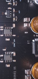
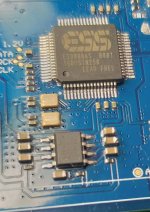
Hello, I have a chinese DAC which has 4700uF for AK4499 chip, driven by an op amp. Supply voltages for op amp are +/-11v. Output voltage of the op amp is 5v and 4700uF. The writing on it is erased. What op amp can be that drives 4700uF? Can it be LME49720 ?
Attachments
In general, directly driving a pure capacitive load with a regular opamp is problematic: the inherent 90° phase shift caused by the compensation added to the pole created by the output cap + output resistance is uncomfortably close to 180°, meaning instability or at the very least severe ringing.
Some opamps fare better than others: LF356 IIRC, and some even tolerate ~infinite capacitive loads; I have no reference to offer right now, but it can certainly be found.
App notes show how to deal with capacitive loads for any opamp, and they are probably the safest solution, even if more components are required

Between output of the op amp and 4700uF there is an inductance with L=100uH and DCR= 1.6 ohm. The same inductance is in the ground. Practically, the op-amp is isolated to 4700uF with those two inductances.
Why would they have chosen this solution?
Why would they have chosen this solution?
Do you have the schematic? Is it not just a coupling capacitor (or supply filter)? Generally speaking, amplifiers (op-amp etc) do not "drive" a capacitor. A coupling capacitor is "large enough" to be "invisible" at audio frequencies between the ~op-amp and the load/output. These op-amps are duals wired as a unity gain buffer, but we can't see the capacitor connections.
It probably saves the day. It is difficult to make a definitive judgment without the specifics of the circuit and an in-depth analysis, but isolating the opamp from the raw capacitance is certainly the way forwardBetween output of the op amp and 4700uF there is an inductance with L=100uH and DCR= 1.6 ohm. The same inductance is in the ground. Practically, the op-amp is isolated to 4700uF with those two inductances.
Why would they have chosen this solution?
All the latest SMSL and Topping models has this for es9068as, es9038pro, es9039pro, AK4499EX, AK4499, AK4497 and maybe more. They has for example a 5v voltage regulator and then a huge RC filter, like 10kohm with 100uF and afther that, from here, the clean 5v go at plus input of a op amp. The op amp is unity gain. At the output of the op-amp there is on 5v and on ground, a 1ohm resistors or an inductance. And finally a big elcap and power supply pin of the D/A chip. Almost all the chinese DAC's has this power supply D/A chip schematic. 5v for AKM VRef, 3,3v for Sabre, etc.
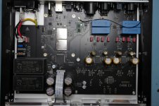
I once responded to another thread on this board, sorry don't remember/have a link, which was discussing the same or a similar arrangement. An op-amp driving a mahoosive capacitor within a DAC. It turns out that this is common practice when trying to develop a low noise reference for the DAC. At face value it should run into all sorts of stability problems but it can and does work for various orders of work. It is possible that whoever implements such horrors is not aware of the issues and has just copied another design that also did not really work but no-one has seen any issues... yet.
Not very clear, but if the output sees the cap through the resistor + inductor, there should be no problem: the closed-loop output impedance of the opamp is orders of magnitude smallerAll the latest SMSL and Topping models has this for es9068as, es9038pro, es9039pro, AK4499EX, AK4499, AK4497 and maybe more. They has for example a 5v voltage regulator and then a huge RC filter, like 10kohm with 100uF and afther that, from here, the clean 5v go at plus input of a op amp. The op amp is unity gain. At the output of the op-amp there is on 5v and on ground, a 1ohm resistors or an inductance. And finally a big elcap and power supply pin of the D/A chip. Almost all the chinese DAC's has this power supply D/A chip schematic. 5v for AKM VRef, 3,3v for Sabre, etc.
More than sure. I checked the routes, too. Almost the same situation with Topping E50 but the capacitor is ceramic of about 10uF and the op am is opa1612.Are you sure that thos 4700uF and chokes are in the supply pins of the chip?
Attachments
I used opamp as a regulated power supply for one audio circuit. My take is that many unity gain stable opamps can work as a power supply with large capacitance at output.
I used OPA551FA with 330 uF connected without any resistor or inductor at the output. Regulator was perfectly stable under any test conditions. Transient response was excellent and with no ringing up to max. output current. Tests with output capacitor from nothing up to several mF of very low ESR capacitors always resulted in perfect stability and clean response under dynamic load conditions.
So, it can work very well and is a simple way to achieve high performance PS or clean voltage reference with only several cheap components.
The inductance, the coil, has L=100uF and R=1.6ohm.Not very clear, but if the output sees the cap through the resistor + inductor, there should be no problem: the closed-loop output impedance of the opamp is orders of magnitude smaller
I want to use AD8397. It looks very nice on paper. Maybe the best for this task is LM7322 but I don't find it anywhere.
unfortunately, the AD8397 doesn't figure in the opamp list of LTspice, but it should be OK. I strongly advise against using a straight cap connection at the output of an opamp, unless it is clearly allowed in the datasheet.
The larger the cap on the output of the op-amp, the smaller the value of ESR + series resistance/inductance required to ensure stability under these circumstances. The op-amp has in effect an inductive output impedance driving a very much higher value of capacitance and forming a resonant circuit damped by capacitor ESR and series resistance. The standard series resonant formular for Q works here and even a tiny (milliohm range) of series R or ESR will ensure a low value of Q and high damping of this resonance with a 4700uF capacitor. Avoid low value low ESR capacitors on their own on the op-amp output as this can encourage high noise gain and even oscillation at the resulting higher resonant frequency.
John
John
An illustration of this effect with a simulation based on real-world components:

The phase margin is 20°, which is sufficient to ensure stability, but the phase grazes 0° at lower frequencies. In principle, the phase could even become negative in this region, but this kind of conditional stability is dangerous in the real world.
The example is relatively extreme, because of the low esr of the cap, but solid polymer Ecaps can do even better, and the LT1056 is a relatively normal opamp
This shows the peaking in the FR:

Again, not catastrophic, but with smaller capacitors it could become problematic.
For all these reasons, I would generally stick with the manufacturers app-notes regarding capacitive loads. Exceptions should be analysed on a case by case basis
The phase margin is 20°, which is sufficient to ensure stability, but the phase grazes 0° at lower frequencies. In principle, the phase could even become negative in this region, but this kind of conditional stability is dangerous in the real world.
The example is relatively extreme, because of the low esr of the cap, but solid polymer Ecaps can do even better, and the LT1056 is a relatively normal opamp
This shows the peaking in the FR:
Again, not catastrophic, but with smaller capacitors it could become problematic.
For all these reasons, I would generally stick with the manufacturers app-notes regarding capacitive loads. Exceptions should be analysed on a case by case basis
In your case, certainly: it will be much larger than anything in the circuit
LT have written design note dn107, about c-load opamps, their term for opamps , stable with capacitive load.
- Home
- Amplifiers
- Power Supplies
- 4700uF capacitor driven by op-amp