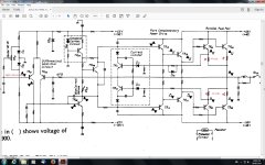
I have 47 volts on the output resistors on my right channel? Ive replaced all the Output transistors with new MJ21193s and pulled MJ21194s from a pro amp that had some MJ21194 OTs blown, most have tested OK on DMM diode test and I used 4 of the best out of about 12. The amplifier is a Sansui AU-11000,Ive replaced all the driver transistors with NOS. The amp turns on and the relay clicks as long as I dont plug the driver board power in from F-2567! If I do plug it in I get 47 v on the emitter resistors and I cant find how its getting there? The driver board power is +65v and -67v. Any suggestions,ideas welcome. The schematic Ive posted is of the left side from the Service Manual but my problem is on the right! Just in case the component numbers get you confused?
Attachments
Last edited:
+47 volts means the output stage is being turned on via TR07. The feedback loop is not causing TR05 to conduct......
The problem could be 'anywhere' but a few quick measurements should show the area of the problem.
With your fault condition TR07 collector will have around +48 volts showing.
TR05 will have less than 0.6 volts across its B-E junction. That transistor could be faulty.
Check those statements above.
Check the supplies are OK. There are four shown on that diagram.
Check the voltage across ZD01 seems reasonable.
If you get stuck then measure and record the voltages on all the transistors and post the readings. Pencilled in on the circuit and that should show in an instant where the fault is.
 OK
OKIm using a 75w DBT because the lamp will glow bright every now and then out of no-where? ZD01 is +10.35v, Tro7 collector reads +49.15v,Tr05 reads,Collector +49.03v. Base -58.15v. Emitter-58.15v.The supply from the big caps is +48v and -48v both sides. I have a Chinese 25 turn sealed Bournes knock off on the bias in place of the real thing until I get a replacement in the post, its right there where the trouble is too? I broke a pin on the origonal one. Hang on I forgot to put the voltages on a circuit?
Last edited:
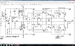
Heres the circuit and voltages.Now I know what you mean by it all becomes clear! The bias VR is turned right down yet its letting through +49v! So that looks like the problem? 😀
Attachments
Have you tried turning it all the other way and then carefully powering up?Heres the circuit and voltages.Now I know what you mean by it all becomes clear! The bias VR is turned right down yet its letting through +49v! So that looks like the problem? 😀
That's as I suspected. TR05 is OFF.
Based on those two voltages it is worth checking TR01 and TR03. If TR01 were open or TR03 leaky then it would give that symptom. Check initially by careful voltage measurement. Each should have around 0.6 volts across B-E
TR07 uses a 'double diode' reference. Check the voltage across the two diodes (or it may be a single package of two) is giving around 1.2 volts.
Also check the voltage on the base of TR01 is 'around' zero. There could be a problem with the offset voltage preset or those diodes (top left).
If you have 47 volts across the output transistor emitter resistors, then you have open resistors.
That's as I suspected. TR05 is OFF.
Based on those two voltages it is worth checking TR01 and TR03. If TR01 were open or TR03 leaky then it would give that symptom. Check initially by careful voltage measurement. Each should have around 0.6 volts across B-E
TR07 uses a 'double diode' reference. Check the voltage across the two diodes (or it may be a single package of two) is giving around 1.2 volts.
Also check the voltage on the base of TR01 is 'around' zero. There could be a problem with the offset voltage preset or those diodes (top left).
OK Ill do that and get back to you Mooly but Id better hit the sack now its 3am already!😕
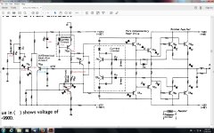
I have replaced all of the driver transistors with NOS from a F-2583 driver board that I was sent instead of the F-2580 driver board.They all tested good in and out of circuit. Still using the DBT with 75w bulb,I got +1.232v across the constant current reference diodes. TR01 base reads,+24v and B-E is +81v. TR03 base reads +23.75v. B-E is +11.60v. DC offset is 9mv on the other channel this problem side is about 25mv DC offset and both dont seem to go down any further? Ive been over and over the driver board circuit checking transistors,diodes,resistors,shorts from solder splatter,etc, and continuity.Electro caps are fairly new and have been checked with a proper capacitor meter,but not for ESR.
Attachments
Those readings sound a bit weird.
TR01 base (as measured from ground) should be close to zero volts. If you can actually measure 81 volts across base and emitter then its faulty (open).
TR03 base should also be around zero when its operating normally, and with 25 mv DC offset at the output that appears to be the case.
So something isn't adding up here.
Edit... and just to be clear... in post #1 you say there was around 47 volts on the emitter resistors. That means the DC offset is 47 volts. Now you are saying it is near zero ? (25mv). If so, then something has changed.
Sorry Mooly, I shouldve taken the DC offset reading before the relay,because the amp is in protection,I wasnt thinking! I was pretty tiered out by then.The voltage is actually 47.90v at connection #18 on F-2567 driver power supply board.I did the voltage test again and TR05 is 0000v across B-E But TR01 base is still 24v and across its B-E is -12v although it reads OK with a diode test? All the transistors are new,Ive just installed them and made sure they are all installed correctly,a diode test in circuit shows TR01 and TR03 to be a matching pair as in matching forward voltages..
Last edited:
🙂 Easily done.
You need to find why TR01 base is at this high voltage. Check the volt drop across both those diodes D01 and D03. Should be 0.6 volts. The wiper of that preset should swing from +0.6 to -0.6 as the preset is turned. Check that.
You need to find why TR01 base is at this high voltage. Check the volt drop across both those diodes D01 and D03. Should be 0.6 volts. The wiper of that preset should swing from +0.6 to -0.6 as the preset is turned. Check that.
D03 reads 0.688v and D01 reads, 0.630v forward volts. Im not game to try and turn the preset while its turned on yet! It reads 0000v across both bias presets on both channels turned right down.The reason Im not game to do it is because the DBT has a good chance of glowing bright when I try to do anything with that trimmer?
Last edited:
Those voltages sound good.
Look at the circuit. The wiper goes via a resistor to the base of TR03 and you mention having around 24 volts on the base. Something is seriously amiss there. The base voltage should be similar to the wiper.
Could the preset be faulty (open circuit wiper) ? You an safely short the wiper to ground as a test.
(The bias preset (that's VR03) won't affect the offset as such)
I can see the wiper goes to the collector on TR05? then onto the emitter of TR09? The trimmer wiper pin is fused to one side pin and the other pin on the trimmer goes via a 1K ohm resistor to the base of TR09.Ive been over and over this circuit so many times I know it off by heart.lol I think it must be that Chinese 25 turn trimmer I bought from ebay and used in that spot? Since Ive installed it Ive realized that when Im trying to adjust the bias all of a sudden the DBT lights up.The amp isnt stable enough to take it off the DBT yet. I was thinking of turning the trimmer over to reverse it but I wouldnt be able to adjust it then! So Im waiting for a replacement in the mail.I cut one of the Chinese trimmers open with a dremel but it looked OK inside? I just hope thats the cause.😕 Aha! I just went back and checked D01, I got -20v forward and +20v backwards?
Attachments
Last edited:
The 'bias' preset goes to TR05 and all that does is control the quiescent current in the output stage. It will not affect offset voltage. If there is doubt over VR03 (the bias trimmer) then you can safely short out TR09 from collector to emitter and forget about the preset for now. Doing that will have no effect on a good and working amp apart from slightly increasing the measured distortion.
Your problem is the 24 volts you are measuring on TR01 base. That could be caused by VR01 being open. You can prove that by connecting the wiper to ground.
Doing both the above takes the presets out of the equation... if the amp is still faulty then you have a problem other than the presets. Try it 🙂
Hang on I just checked back on D01 and got -20v forward voltage and +20v backwards voltage so it looks like that diode is blown? It read OK before,then it didnt? Its 1am here so Id better get an early night,Ill do those tests Mooly and get back to you with the results.
Last edited:
- Status
- Not open for further replies.
- Home
- Amplifiers
- Solid State
- 47 volts on output resistors?