Hi at all !
I am finishing a tube amp, with 6e6p 45 300B tubes.
45 and 300B have filament current DC.
The 45 have 3 Vac , Diode Full Wave , 10.000uf , 10.000uf and 2.5Vcc.
But, when i bypass the cathode resistor , in one of them ( Left side) the plate voltage of 45 tube
scales from 240v to 270v and the -34v goes down to -27v.
In this moment I'm not sure if it goes higher than -34 or goes down to -27v.
It's late night and I'm tired of think.
Change side the resistors 1K.
Swap the bypass capacitors sideways, and always the left side is the one with those changes.
Somebody could help me ?
Attachments

Last edited:
Please post a more complete schematic.
Bypass capacitor polarity reversed?
Bypass capacitor not rated for 63V?
DC coupled from the 6E6P?
Circuit is oscillating? (sub audio, or above audio frequencies, or you would have heard it).
Wiring error?
Try swaping 45 tubes from channel to channel.
Again, a schematic would be nice, want to get this solved within 1 page (10 Posts).
6A3sUMMER : Thank you.
After breaking my head and not understanding why when putting the cathode bypass capacitor, the anode voltage rises and the cathode voltage goes down, connect the input RCA to see if something changed and the problem was solved.
Could it be that when the input RCA was free, the 45 oscillated or something similar?
Santiago
Without a complete schematic, amp and power supply . . .
I would be blindfolded, rotated around, and shooting an arrow at the target.
I miss almost every time.
I would be blindfolded, rotated around, and shooting an arrow at the target.
I miss almost every time.
From what you describe the cathode voltage drops when placing that cathode bypass capacitor. As a result the valve is conducting more so it is normal the anode voltage drops. Output triodes have restrictions on the size of the allowed grid leak resistor!
Is the RCA input connected directly to the 45 grid?
No input tube?
Or is the input tube direct coupled to the 45 tube?
We need to see a schematic, please.
No input tube?
Or is the input tube direct coupled to the 45 tube?
We need to see a schematic, please.
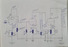
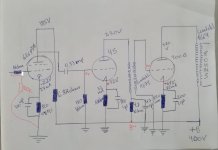
Looking at the input stage the numbers do not add up. If you drop 400-185=215V over a 6800R resistor, the current involved is 215V/6800R=31,6mA.
If you have a 820R cathode resistor, that current should give 820x0,0316=25,9V cathode voltage. Please recheck!
If you have a 820R cathode resistor, that current should give 820x0,0316=25,9V cathode voltage. Please recheck!
I hope you did not mount the Interstage transformer and Output transformer next to each other.
I hope you aligned the coils of them, 90 degrees to each other.
I hope you did not use a magnetic steel chassis.
You can make an oscillator by putting those transformers together, mis-aligning their orientation, or using steel chassis.
It may be just below the level of oscillating, and then you change something . . .
The speaker, the input signal source and cable, probing around with a DMM meter lead wire and probe tip, etc.
When something is not quite oscillating, just a change of the above may cause it to go over the limit.
Do you still have the problem?
Last edited:
Hi 6A3sUMMER.
No, I don't have the problem anymore.
When you pointed out to me that it could be that the channel was oscillating, just by putting the RCA cable on the input, the problem disappeared.
The amp works fine, it sounds good.
I think that with 375V and 1K cathode resistor , the voltage should be around -70v.
In my previous 300B amps the cathode voltage was there.
But know i have, only -63v on cathode with 375V and 880ohms.
I just need to know if that's okay.
But the amp is sounding good.
santitrucco,
Your schematic had a 820 Ohm resistor for the self bias resistor.
Does it have a 1k resistor for self bias now?
375V plate
63V filament (for a DHT, the filament acts in the place of a Cathode).
375V -63V = 312V Plate to filament
63V/820 = 76.8 mA
63V/1k = 63 mA
Both of those currents are reasonable versus the resistance of the self bias resistors.
One of the standard/classic operating conditions for a WE 300B is:
300V plate to filament; -61V bias; 60mA.
Tubes will vary from tube to tube.
Without even looking at the curves for the 300B, I am pretty sure that this is normal too:
312V; -63V; 820 Ohms; and 76.8mA.
I would say that with 312V, 63mA, and 63V bias, your tube is well within the range that I would expect for a good tube.
The same goes for 312V; -63V; 820 Ohms; and 76.8mA.
I will try and find a set of curves to verify that . . .
. . . Ok, that is close to the WE curves.
Congratulations!
Worry less,
Enjoy Listening More!
Last edited:
- Home
- Amplifiers
- Tubes / Valves
- 45 tube Cathode Bias Problem.