I have a pair of Hashimoto H-20-7U and would like to build an SE Class A amplifier with sufficient sensitivity to avoid an external preamplifier.
For the tubes I am considering a EML45 Mesh
I have very efficient speakers >100 dB, therefore the two watts of the 45 is not a problem.
I would appreciate it if someone could point me in the right direction.
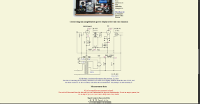
In the research I did I found these two schematics.
I really appreciate your help with this project!!
For the tubes I am considering a EML45 Mesh
I have very efficient speakers >100 dB, therefore the two watts of the 45 is not a problem.
I would appreciate it if someone could point me in the right direction.
In the research I did I found these two schematics.
I really appreciate your help with this project!!
Attachments

My recommendation with these kind of 2 stage SE amps is to always pay special attention to the input tube, as much as the output tube. Using a 45 in the output doesn't guarantee you a good overall DHT type sound. I generally use a 26 or a 27 mesh plate. Other possibilities are 01A, 10Y, 2P29L etc. These input tubes have a gain of 8 to 10 so they really want to see an output tube with a gain of 8 or 10. For this reason I use PSE 4P1L. For your speakers you could probably use a single 4P1L, driven at 40mA. You need a solid case to avoid microphonics, maybe decoupled. 4P1Ls are not usually microphonic in the output stage with due care.
I would personally prefer a 26 into 4P1L to an average input valve driving a 45. A 6SN7 input tube might be OK into a 45, though. That works.
I would personally prefer a 26 into 4P1L to an average input valve driving a 45. A 6SN7 input tube might be OK into a 45, though. That works.
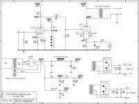
Well, I built a pair of 45 SE Monoblocks about 17 years ago using Hashimoto H507S OPTs and Hashimoto power transformer and filter choke. Note that the Hashimoto OPTs invert the phase, meaning that the signal input to the grid of the 45 will be the same phase as the OPT output.
Feel free to use my schematic... note that I do pad the open winding end of the primary, so as not to have that part of the winding "flapping in the breeze" (A David Manley quote). Also, the gain of the 5814 input/driver is around 43dB, or 150 V/V and can easily drive the 45 grid beyond it's BIAS points. The design is also flat within 1dB to 50KHz. Overall gain is about 250mv for 1-watt output, hence no need for a separate preamp.
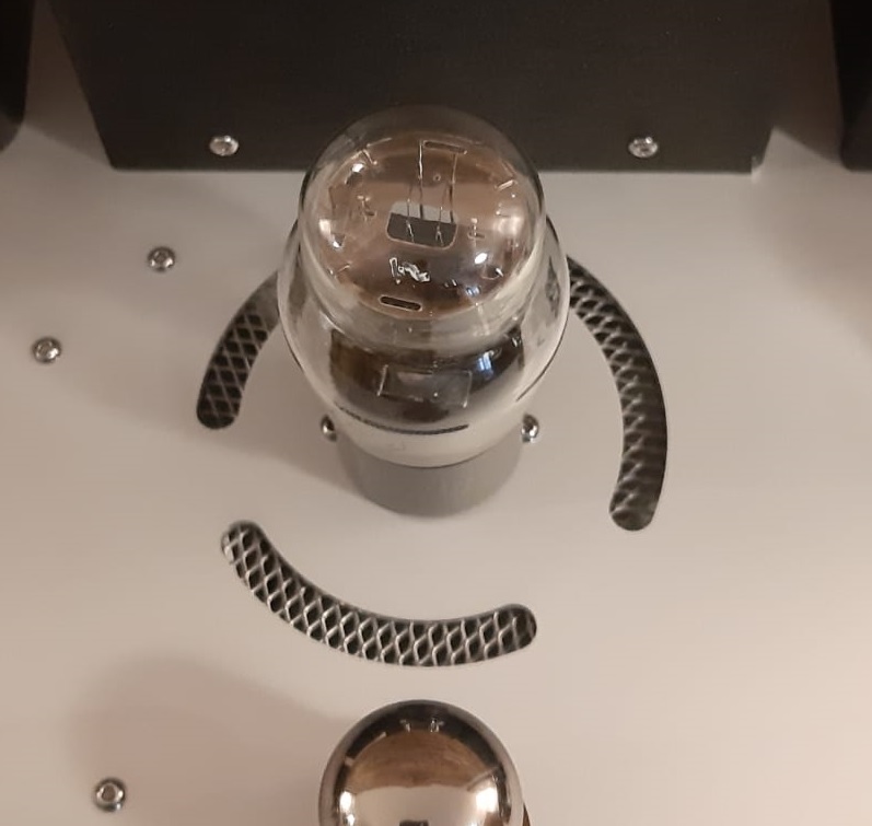
Finally, while I've not used the EML 45Mesh tubes, I do have a pair of the EML45 tubes... these are not really a 45.... similar in spec, but not quite the real deal. They need some higher bias current to get them sounding decent and I found they are quite sensitive to any mechanical excitation, including music playing from the speakers being close to the amps. In short, I don't use them, but have numerous matched pairs of NOS 45 tubes, which I prefer.
Good luck with your project.
Feel free to use my schematic... note that I do pad the open winding end of the primary, so as not to have that part of the winding "flapping in the breeze" (A David Manley quote). Also, the gain of the 5814 input/driver is around 43dB, or 150 V/V and can easily drive the 45 grid beyond it's BIAS points. The design is also flat within 1dB to 50KHz. Overall gain is about 250mv for 1-watt output, hence no need for a separate preamp.
Finally, while I've not used the EML 45Mesh tubes, I do have a pair of the EML45 tubes... these are not really a 45.... similar in spec, but not quite the real deal. They need some higher bias current to get them sounding decent and I found they are quite sensitive to any mechanical excitation, including music playing from the speakers being close to the amps. In short, I don't use them, but have numerous matched pairs of NOS 45 tubes, which I prefer.
Good luck with your project.
Attachments

Agreeing with Andy, should be determined the VAS stage: gain, structure (tube type, anode load type -passive R, inductive choke/IT, active load- etc.).
The power tube operating point determines the grid swing maximum peek (up to A1 limit), so VAS gain calculable, tube selectable.
The max. grid swing determines the VAS stage -minimum- anode swing, from this -and tube type- the VAS tube operating point also computable.
The power tube operating point determines the grid swing maximum peek (up to A1 limit), so VAS gain calculable, tube selectable.
The max. grid swing determines the VAS stage -minimum- anode swing, from this -and tube type- the VAS tube operating point also computable.
I had the Yamamoto 08S and thought it was a very good amplifier. I had the EML solid plate 45 and thought they sounded good, but eventually enjoyed a pair of Sylvania 45s as the best sounding in my setup. I thought my Zu DW speakers needed more power than the Yamamoto could provide. It has been a few years, but I recall I changed the coupling cap and added some capacitance to the driver tube's plate supply (B1).
There's a lot to be said for Gordon Rankin's Bugle. It's a simple build, sounds great, and with a 5751 driver the amp will rock with your speakers.
Then you could think about more exotic drivers as Andy suggests - you may prefer the sound, but complexity increases.
Don't know how to link it but the first hit of a Google search for "Bugle 45 tube amp" has the link to the PDF on DIYAudio.
Then you could think about more exotic drivers as Andy suggests - you may prefer the sound, but complexity increases.
Don't know how to link it but the first hit of a Google search for "Bugle 45 tube amp" has the link to the PDF on DIYAudio.
HiNote that the Hashimoto OPTs invert the phase, meaning that the signal input to the grid of the 45 will be the same phase as the OPT output.
Sorry but not...
The tube anode loaded amplification stage is one that inverting phase for 180deg.
Transformer can revert phae or not depend on how iti is connected.
.
BUT one major thing is somehow missing with SE OTs connection in citcuit.
The start of the primary windings, that 1st one turn close to the iron core, has to be connected to Anode of amplifying tube.
Other end, final layer with last turn has to be connected to Vb.
Secondary is free to adjusting the phase in phase or out of phase.
(In some open OT we can clearly see where is that firat turn of primary close to the core. But in boxed OT units we can not perform this very simple detection...)
.
For one stage SE tube - signal on the grid is in phase, at anode is OUT of the phase, so for secondary to be in phase as input we have to revert secondary connection.
.
For 2 stage of SE tube amplifier, first tube invert phase, second bring back in phase. So OT at output power tube has to be connected in phase.
.
The output transormer is connected on secondary as a result of number of gain stages used in amplifier.
But always the first turn close to the core going on Anode.
So Phase can be regulated on secondary only.
.
The parkings are standard with black dots. and this is about phases.
BUT ususaly we dont have clear info where is that first turn?
In some papers it is marled the same as BLACK dot...
.
If it is, the primary pin marked with black dot is always going to Anode, another end of Prim. is on the Vb.
And With the BLACK dot on secondary we can choose the phase corresponding to number of stages in our amplifier.
.
Same is for Line transformer employing as anode load.
.
So maybe the best way is to check with manufacturer where is beguining of first turn?
And how it is related with black dot marking?
.
And remeber black dot in transformer markings is not representing "ground"...
.
cheers 🙂
Last edited:
And
Hashimoto H-20-7U with 7Kohm 30H/60mA
is a better choice than
Hashimoto H507S with 7Kohm 20H/40mA
because of higher primary inductance that will give more propper bass response.
But it is questionable and should be checked with internal resistance of 45
that is aproximatly 2 x 2A3 Ri...
.
Another thing from the schematics, is -47V and -55V grid bias.
So to keep input signals in negative range we have to input max of 2 x -Ug
94Vp-p or 110Vp-p at the grid...
IF we want input sensitivity of say 2Vrms that is around 5.64Vp-p
(Also some sources have more than 2Vrms output... it will be no mistake to allow more V at input...)
You need a input stage of
94Vp-p / 5.64Vp-p = 16.6 times
or
110Vp-p / 5.64Vp-p = 19.5 times
Bare in mind that the gain is always smaller than mju factor of the tube.
.
Also You have to check driver requirements in context of capacitances.
But that will be not a huge issue and the main factor for that is Ri of driving tube
Last edited:
@Zoran:
My statement about phase on the Hashimoto OPTs is correct... perhaps you didn't understand my statement. Most SE OPTs do not invert phase, so a 2-stage amplifier results in an amplifier that has the input and output in phase. The standard Hashimoto SE OPTs (H-507S and H-203S) invert the phase from primary to secondary. My posted 45 schematic is a 3-stage amplifier and the output is in phase with the input. Note that Hashimoto recently added a version of their 7-watt SE OPTs with standard phase for use with a 2-stage amplifier. These are the H-507D and H-203D and specifically listed for a 2-stage amplifier circuit. Current Hashimoto catalogue attached.
As for using the 20-watt OPT versus the 7-watt OPT, at 2-watts output, there's not going to be a significant different in low frequency response. My 45 SETs schematic above if within 1dB from 25Hz to 50KHz within 1 dB. Low frequency response is purposely tailored to drop off after that, as a 2-watt amplifier isn't going to handle extreme low frequency with most high efficiency speakers. Granted the 20-watt OPTs are a different core construction than the 7-watt OPTs, which is a plus, but there is the added expense as well. I simply picked a cost point and overall chassis size for these monoblocks. I have the 20-watt OPTs with the 3.5K primary which is used for a pair of 2A3 single plate tubes, albeit in a larger chassis.
Attachments
Hello everyone,
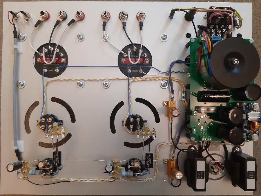
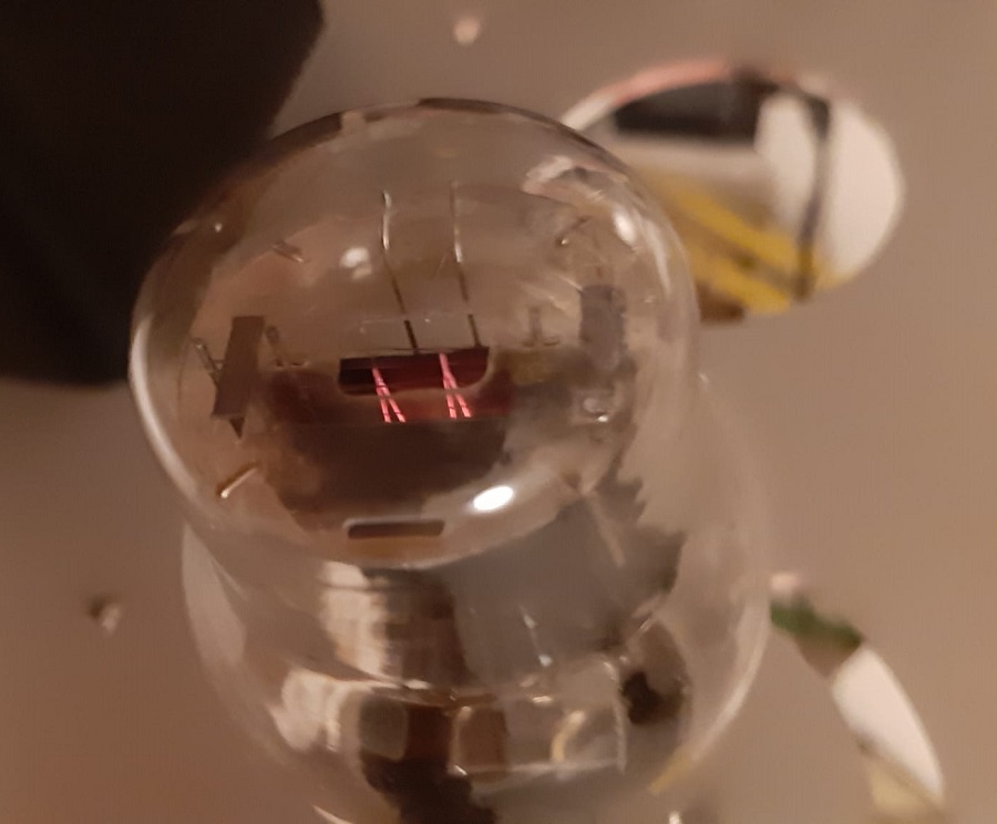
Like many of you, I'm a fan of power triodes, particularly the famous 45 triode.
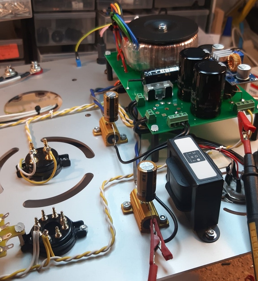
Below, I'm sharing with you an example of an SE45 amplifier from my collection.

greetings. Tony
Like many of you, I'm a fan of power triodes, particularly the famous 45 triode.
Below, I'm sharing with you an example of an SE45 amplifier from my collection.
greetings. Tony
Thank you very much for your valuable feedback I appreciate it.
Now I have a lot of information to digest and I'm new to this type of amplifier typology.
I will try my best to make a schematics and then I will share it here to hear your opinion.
once again, thank you to all !
Now I have a lot of information to digest and I'm new to this type of amplifier typology.
I will try my best to make a schematics and then I will share it here to hear your opinion.
once again, thank you to all !
- Home
- Amplifiers
- Tubes / Valves
- 45 SE class A Amplifie