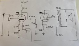
So this is my idea for a 42 SE amp with a 75 driver. I have a couple of 76 tubes that could work as drivers too, but decided on the 75 driver since the extra gain could come in handy for feedback application. There are a couple of issues still, so any suggestions are much appreciated.
- The feedback circuit isn't calculated as much as borrowed (all right, stolen) from an amp with a 6V6 and a vaguely similar driver tube, so I'm not sure if this will work at all. Is plate to plate feedback an option?
- Is UL operation a good idea at all with the 42? I could run it in triode if I can get by with less than a watt, and a screen supply for pentode mode isn't much work or parts.
- My drawing doesn't have grid stoppers, but I will use them.
Attachments
Last edited:
- The feedback circuit isn't calculated...
It does not need to be calculated. You can adjust it simply as follows:
Without GNFB, measure the the gain from input to the speaker (connected to dummy load) at output level clearly below clipping, use an oscilloscope to verify this.
So you need a signal source, oscilloscope or audio voltmeter and resistive dummy load.
Put some 10k...20k trimmer resistor or potentiometer in place of feedback resistor (3k3 in schematic) and adjust the gain 6...14 dB lower than the open loop gain was.
As you have achieved the amount of GNFB you like (between 6 to 14 dB), measure the resistance of the trimmer resistor and then put a fixed resistor of same value in place of feedback resistor.
Why the upper limit of GNFB is 14 dB ?
Higher GNFB may cause instability with some output transformers and speaker loads.
These can be avoided with certain fine tune process. To do these require some more experience and test equipment.
- Is UL operation a good idea at all with the 42?
Yes it is.
Yeah, I forgot the secondary ground on the drawing, I have to add that 🙂 And also a 1M grid resistor on the 75, just in case.
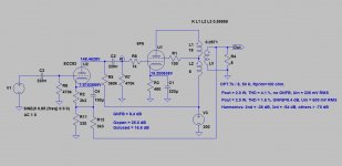
Hey, thanks for taking the time to run a simulation! This is great info, now I just have to build it 🙂
Maybe worth spitting R9 say 330k and 33k to HT. Add 10-22uF to ground. This will stop power supply hum getting to the first plate. A quick simulation with some AC on the V3 will tell.
Last edited:
Of course the real circuit with actual components require supply voltage filtering as you described, but LT Spice simulations do not require such operation, because the power supply V3 represent zero ohms AC-impedance.
- Home
- Amplifiers
- Tubes / Valves
- 42SE amp idea