I am thinking of building an amp for driving the electrostatic panels of my ML Aeon hybrids.
They aren't an easy load, with the impedance dropping to below 1.32r at 20khz, but the crossover is at 450Hz so the opt does not need to be anything special.
I'm not experienced with tube amps, so don't know whether I want an opt with UL taps, what HT I should use, and whether to stick to a pair of EL34s, of use something like KT88, or KT120s.
Please point me to a suitable schematic
A pair of these mains transformers seems suitable. Power Transformer Guitar Amp Valve Tube 6L6 DIY Supply Push Pull FIRM Components | eBay
and have a 40vAC winding for biasing.
For opt Hammond 1650HA 6.6k 200ma
Last edited:
One EL34 draws 1.5A filament, the above transformer seems too small forI am thinking of building an amp for driving the electrostatic panels of my ML Aeon hybrids.
They aren't an easy load, with the impedance dropping to below 1.32r at 20khz, but the crossover is at 450Hz so the opt does not need to be anything special.
I'm not experienced with tube amps, so don't know whether I want an opt with UL taps, what HT I should use, and whether to stick to a pair of EL34s, of use something like KT88, or KT120s.
Please point me to a suitable schematic
A pair of these mains transformers seems suitable. Power Transformer Guitar Amp Valve Tube 6L6 DIY Supply Push Pull FIRM Components | eBay
and have a 40vAC winding for biasing.
For opt Hammond 1650HA 6.6k 200ma
a 2 x EL34 + one or two pretubes. To be at the limit already at planning stage
is a bad start of a project.
Good point - didn't check the heater requirements.
I found this schematic:
OddWatt Audio 5751 SRPP / KT88 Push-Pull Monoblock Tube Amplifier Kits
I found this schematic:
OddWatt Audio 5751 SRPP / KT88 Push-Pull Monoblock Tube Amplifier Kits
Why not drive the ML panels directly? You can leave the bias supply in the ML electronics and drive the panels directly from a tube circuit. Based on the super duper low impedance at 20kHz, there's probably a big step-up transformer in there. Why step the amplifier output down, only to be stepped back up in the speaker? If anything, you could go up from the output of the amplifier to the panels if necessary, but with only one transformer.
Its a thought and ML might let me have the schematic, but as they are mains powered, it probably would mean major mods.
It could literally be a step-up transformer and a big *** voltage multiplier acting as a bias supply.
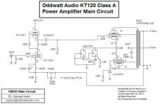
Trying this:
I've decided to monoblock this design using a different otp - a Hammond 1650H which has a 6.6k primary and 40% UL taps.
Also I was thinking of using a pair of 6L6GC rather than EL34, or maybe KT88.
Power transformers have 360v 250ma secondary with a bridge rectifier and CRC filtering.
Other photo is of the ML Quest's electronics, and possible similar to the Aeons, so probably not feasible to modify them.
Attachments
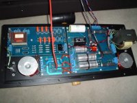
Yeah, so those electronics are a crossover, a voltage multiplier, and a step-up transformer. I would absolutely modify them!
You think you'd really need 40 watts output power from a true class A PP amplifier, so you'd need a pair of output tubes with a plate dissipation ration of 40 watts at least - per tube.
Best regards!
Best regards!
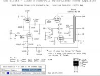
Since the basic circuit is one of mine I thought I would chime in. Swap the output transformer for a 3.5K one with at least 300 (more is better) ma balanced dc current capability (the Edcor 70 watt ones are fine). Then swap the tubes for KT120s. Parallel a pair of LM317HVs. They work fine in parallel if from the same lot. Many such arrangements are in commercial and diy amps we put out over the past 6 years. The schematic I attached shows two separate power levels for the tubes. Approximately 25 and 40 watts RMS. If all you want is the higher power use a single 5 ohm (4.8 calculated) resistor. Be aware that there are some Tungsol KT120s flying around that were made about 3-4 years ago that do not meet spec for continuous dissipation. Some barely handle 60% before red plating. Send any such ones back to the seller. I even got some directly from the US importer. PSVANE KT120s are not suitable at this dissipation as well.
Attachments
Possibly. A pair of them will yield about 36 watts in PP class A mode (plate voltage 300 V, plate current 130 mA, plate to plate Z 4 kohms).
Best regards!
Best regards!
A 40W per channel Class A amp is going to run mighty hot, everything will be very hot and your power consumption will be a lot higher constantly. Overall it sounds like a bad idea to my simple mind.
It might be sacrilege - but I would go digital.
Shoog
It might be sacrilege - but I would go digital.
Shoog
Since the basic circuit is one of mine I thought I would chime in. Swap the output transformer for a 3.5K one with at least 300 (more is better) ma balanced dc current capability (the Edcor 70 watt ones are fine). Then swap the tubes for KT120s. Parallel a pair of LM317HVs. They work fine in parallel if from the same lot. Many such arrangements are in commercial and diy amps we put out over the past 6 years. The schematic I attached shows two separate power levels for the tubes. Approximately 25 and 40 watts RMS. If all you want is the higher power use a single 5 ohm (4.8 calculated) resistor. Be aware that there are some Tungsol KT120s flying around that were made about 3-4 years ago that do not meet spec for continuous dissipation. Some barely handle 60% before red plating. Send any such ones back to the seller. I even got some directly from the US importer. PSVANE KT120s are not suitable at this dissipation as well.
Many thanks for the info.
I have already ordered a pair of Hammond 1650H OPTs with 6k6 primaries so what would you suggest for V+ and CC resistors and tubes?
Mains transformer is 360v 250ma, 6.3v 3.2a - per channel. A pair of 6L6GC or KT77+ an Ecc83, is just possible for the heaters from this transformer.
Actual power into 6r is not that critical provided it's around 25w minimum, but more would be better.
Last edited:
Hi, Unfortunately you aren't going to get the 40 watts you wanted. The B+ will be too low (the design uses 450 as a target voltage). The current available will be on the short side as well. However, my personal favorite for similar amps is to reduce the current to about 65ma per tube in class A U/L and have a 425-475 B+. This could be in your range of gear. Using solid state rectifiers and capacitive input filtering it could work. Your output trannies while not 8K would be almost in the range that seems best. Such amps would deliver about 20 watts RMS and sound really sweet. On the power remember that the "loudness" is not a linear function of power input. So half the power is not half the loudness. You might not even notice the change.
It's a starting point and as its just for the electrostatic panels of the Aeons, may well be sufficient.
I will do some measurements with Picoscope into a 5r dummy load and into the Aeons and report back in due course.
But at least it will not be a major job to upgrade the transformers and add a second LM317HV. (the metal work is my least favourite part of any project)
Many thanks for your input.
I will do some measurements with Picoscope into a 5r dummy load and into the Aeons and report back in due course.
But at least it will not be a major job to upgrade the transformers and add a second LM317HV. (the metal work is my least favourite part of any project)
Many thanks for your input.
Gofar99, I've been doing some research into HT delays and standby switches and there is a claim that these are based on old wives tales and not necessary, or can actually be damaging.
The Valve Wizard
So I am planning on not fitting any delay, and also will elevate the heaters as shown on this page:
The Valve Wizard
I.e. using a pair of 220r resistors to form a virtual centre tap to which the elevation voltage is connected.
My transformer does not have centre tapped windings, but it does have a separate 40v ac winding which would be an alternative way to elevate the heaters to about 60v if full wave rectified.
Also, should not the relay be placed in the AC part of the HT supply to reduce arcing? (I couldn't find a relay with 450v DC contacts which is another reason for dispensing with the delay).
The Valve Wizard
So I am planning on not fitting any delay, and also will elevate the heaters as shown on this page:
The Valve Wizard
I.e. using a pair of 220r resistors to form a virtual centre tap to which the elevation voltage is connected.
My transformer does not have centre tapped windings, but it does have a separate 40v ac winding which would be an alternative way to elevate the heaters to about 60v if full wave rectified.
Also, should not the relay be placed in the AC part of the HT supply to reduce arcing? (I couldn't find a relay with 450v DC contacts which is another reason for dispensing with the delay).
Hi, Whether or not you use a delay depends on several factors. It no longer makes a lot of sense just for tube life....however there is another reason I use it. I use solid state power supplies. At turn on in less that one second they will reach the peak B+ voltage roughly equal to 1.4 times the transformer's RMS value. So if the tranny is rated at say 375-0-375 and you use a pair of SS rectiifiers it will get to about 525 VDC nearly instantly. Since the tubes are cold they will not conduct for several seconds. Thus your filter caps will see that value. Most are rated at 500 or less. They will handle over voltages for a while.....how long depends on the brand etc. 600 or higher voltage caps are rather pricey and IMO not needed if you use a delay. So with a 60 second delay (often less is fine) the tubes will conduct as soon as you turn on the B+. In most of my designs that means the resulting B+ will be in the 425-450 range which is below the filter cap ratings. I design things with the thought in mind of reliability and like long capacitor and tube life. A prototype stereo integrated version of the amps is now runing in my room with the original blue glass JJ KT88s from my first project that used them back in 2008. They are just fine and BTW so are the original amps. I do not use delays BTW in lower powered amps, but I do use caps rated well above the peak B+ voltage expected at turn on.
You are correct that relays rated for high voltages are scarce. However, if you think about it the relay is seeing pulsing DC and not pure DC in the locations I use them. This looks much like AC to them. Also I use a spark suppression cap and resistor across the contacts. This arrangements works fine and is used in the diy amps and the commercial ones. There are hundres of them out there now. Only one relay ever failed and it was due to a defective resistor in the spark suppression circuit.
Good listening
Bruce
Last edited:
- Home
- Amplifiers
- Tubes / Valves
- 40watt push pull class A amp suggestions