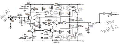
Looks fairly standard topology.
Except pairing of driver transistors, I haven't seen that before, they usually just put in beefier single transistors.
Except pairing of driver transistors, I haven't seen that before, they usually just put in beefier single transistors.
Yes very standard apart from the doubled-up drivers. Probably easier and cheaper just to use a pair of TO-126 drivers, and that way you can eliminate the four current sharing emitter resistors.
What's the Vdrop across those rail filter resistors? 40W seems a little on the low side for that topology with 36V rails.
What's the Vdrop across those rail filter resistors? 40W seems a little on the low side for that topology with 36V rails.
I think the 40W/8Ω limit is in line with the limitations of 2N5551 - even 2 of them, since they can only dissipate 1W between them, with no heatsink. I think a 70W/4Ω rating is just being hopeful, even using good, high gain output transistors like those Sankens.... they usually just put in beefier single transistors.....
In manufacturing, a pair of T0126 transistors is more expensive than all those resistors and 4 cheap TO92 types. This design is obviously about cheap but I'd say it was unwise for DIY. A complementary pair such as BD139/40 or 2SD669/B649 clones with even small heatsinks will be more robust and handle the typical mistakes made by experimeters.
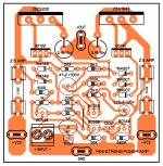
The "mini strong" design also has a terrible PCB layout. Just look at where the + ve rail supply connector is - right next to the input terminals.Simpe amp to diy
Guys, sometimes you have to use some knowledge of electronics and basic electrical theory rather than aim for geometric prettiness or convenience. There are electromagnetic fields around the conductors and the higher the peak currents, the more noise and distortion arises from gross layout errors like this. In fact, it's more important to audio than simulations, PCB software or all your graphic skills.
The "mini strong" design also has a terrible PCB layout. Just look at where the + ve rail supply connector is - right next to the input terminals.
Guys, sometimes you have to use some knowledge of electronics and basic electrical theory rather than aim for geometric prettiness or convenience. There are electromagnetic fields around the conductors and the higher the peak currents, the more noise and distortion arises from gross layout errors like this. In fact, it's more important to audio than simulations, PCB software or all your graphic skills.
Hello sir Ian Finch, can u tell me is this circuit(amplifier) for make waste of
time.Then tell me which 70w to 100w amplifier make for my music system please. One more thing i am not so professional in electronic field like U
I'm listening to this one right now:
Retro Amp 50W Single Supply - Page 22 - diyAudio
with 60 v power rail & NTE60(MJ15003?) output transistors I've had it up to 24 Vac on my 8 ohm speakers. This is about 72 W. That was half seconds at a time, loud parts of Rihanna Shut Up & Drive
The PCB layout is back on page 1 or 2. I built mine point to point with wire and bare board.
The cool thing about a single supply amp with output capacitor for newbies, if you make a bad solder joint that pops loose in play, it doesn't put DC on your speaker and melt the coil insulation or rip the surround rubber.
I used TIP41C/42C for drivers which are cheap, with heat sinks. Top octave piano and high frequency percussion seem a little distorted compared to RCA 5 digit TO5 drivers. If I build it again I'd use KSA1220/KSC2690 for drivers which just became available at mouser. Or for $1.60 each, MJE15032/33. The original BD139/140 from Phillips were fine, but the Fairchild copies we can buy here are not specified for speed, could be as slow as TIP41c/42c. (3 mhz)
My TO220/TO126 heat sinks are cut up window frame, so those are free. Use them with compound, that is what was wrong with the OP 40 W design, quad TO92 .5 W transistors as drivers, which don't shed heat to a sink with that round surface.
Last edited:
- Status
- Not open for further replies.
- Home
- Amplifiers
- Solid State
- 40w audio amplifier