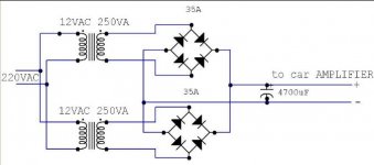
i want to build a simple power supply to car amplifier for a car store display..... in the pic it is a power supply for 1 amp....
it is out a 40A...in 16.8VDC........ i already build it and try this....
but if i up the power - of the amplifier (music) the led of the amp... start to blinker...
why ??? 40A no enough ??? or the 4700uf is not enough ???
this is a normal amp.... 1000W peak... the fuse in the amp is 20A x2 (if is metter)
Attachments
Under heavy load your circuit will only put out 10.5V DC, the RMS voltage minus the rectifier drop.
A real 12V 40A supply would have a 34VCT transfomer and a two diode bridge feeding a regulator. 13.8V out(12V nominal) + .7V diode drop + 2.5V for the regulator = 34VCT
A switching supply would have different requirements, usually beyond DIY.
A real 12V 40A supply would have a 34VCT transfomer and a two diode bridge feeding a regulator. 13.8V out(12V nominal) + .7V diode drop + 2.5V for the regulator = 34VCT
A switching supply would have different requirements, usually beyond DIY.
Your transformers will probably be fine, and i guess the amp won't mind the extra voltage, maybe 17V or so when unloaded. But you need a bigger capacitor, you need one at least ten times as big.
megajocke said:Your transformers will probably be fine, and i guess the amp won't mind the extra voltage, maybe 17V or so when unloaded. But you need a bigger capacitor, you need one at least ten times as big.
yes the amp won't mind the extra voltage - 15-17V
soo u say that i need a 47000uf ? or more?
and i i build a 80A like the pic but with 4 transformer...
and i connect them 611000uF (4700uF x 130)
it will be good???
I use a one farad capacitor on my test bench for car audio amps.....and the transformers look too small in my beliefs......I have a 1500kva transformer and it wants to stall when burning in some serious amplifiers.....I got around this by charging up some Gel-cell marine batteries..but thats not the answer to your question
DIRT®
DIRT®
Dj BASS AMP said:
yes the amp won't mind the extra voltage - 15-17V
soo u say that i need a 47000uf ? or more?
and i i build a 80A like the pic but with 4 transformer...
and i connect them 611000uF (4700uF x 130)
it will be good???
hehe... You'll need way more than 47,000uF of capacitance, here. In fact, the equation to determine just how much capacitance you will need is:
C = I/(dV*f)
Where C is farads, I is amps, f is 120 hertz and dV is ripple in volts peak-to-peak. What amount of ripple your amplifiers can tolerate depends heavily on the switching power supply inside them, but let's make it 5%, or about 600mV. The capacitance needed will be... 555,555uF. It will be absolutely necessary to obtain this amount of capacitance through paralleling several smaller capacitors in order to split the current up among them. A single "farad" capacitor, like the type so popular in car audio applications, will not have the ripple current rating (usually between 3 and 5 times the average current is necessary!) to cope with this duty.
Note that a 12.6V secondary voltage will be perfectly adequate as long as there is plenty of capacitance and strap copper connections to carry the current!
jeffreyj said:
. The capacitance needed will be... 555,555uF. It will be absolutely necessary to obtain this amount of capacitance through paralleling several smaller capacitors in order to split the current up among them.
555,555uf it is good for 80A power supply??
and what better.... 1F - car capacitor.... or 1F (from a lot of 4700uf)
I don't know where you guys learned to push electrons, but the way I learned it it goes:
12VAC goes to 17V peak every 8.3mS(on 60hz), but it also drops to 0V every 8.3mS too. The Root Mean Square of this is 12V. While the cap can store energy from the 17V peaks and release it during the 0V periods, the capacitor creates no energy, it only stores it to be released later.
Diodes drop voltage across them, about .7V nominal, more at high currents. I was being charitable when I only subtracted 1.5V for a four diode bridge. What kind of diodes are you guys using that have no losses?
The power factor on a cap input filter with a hugh cap is really poor, around 0.7, this means that your two 250VA transformers will pull 500W in and only put 350W out. So at the peak of 17V with a 1 Farad cap you will get less than 20A out, even though the transformer is rated at 40A RMS. And I forgot to subtract the rectifier loss, so it will be more like 15V at 20A
One other thing: If you use a hugh cap you also risk blowing the rectifiers. Even though the thing will only put out 20A the peak charging currents every 8.3mS will only be limited by the DC resistance of the transformer wire, the hugh cap will only draw current on the very peak of the sine wave and will act like a dead short.
Maybe a quick trip to the local community college book store would be in order?
I have measured the power factor of a diode bridge feeding a big cap from the ac mains with this fancy Voltech PM1000 digital meter meant specifically for this kind of measurement, and it measured 0.6, an even lower figure. Based on that, your 500VA's worth of transformers is only going to be able to put out 300 watts. Bridge losses again are extra.djk said:The power factor on a cap input filter with a hugh cap is really poor, around 0.7, this means that your two 250VA transformers will pull 500W in and only put 350W out.
djk said:I don't know where you guys learned to push electrons, but the way I learned it it goes:
The power factor on a cap input filter with a hugh cap is really poor, around 0.7, this means that your two 250VA transformers will pull 500W in and only put 350W out. So at the peak of 17V with a 1 Farad cap you will get less than 20A out, even though the transformer is rated at 40A RMS. And I forgot to subtract the rectifier loss, so it will be more like 15V at 20A
One other thing: If you use a hugh cap you also risk blowing the rectifiers. Even though the thing will only put out 20A the peak charging currents every 8.3mS will only be limited by the DC resistance of the transformer wire, the hugh cap will only draw current on the very peak of the sine wave and will act like a dead short.
i dont ask u if it is peak or not or what learned...
i ask what will be better.... 1F - car capacitor.... or 1F (from a lot of 4700uf)
"i dont ask u if it is peak or not or what learned...
i ask what will be better.... 1F - car capacitor.... or 1F (from a lot of 4700uf)"
I'm sorry you don't seem to understand Circlotron or myself, we are trying to help you benefit from mistakes we have made in the past:
Your transformer is too low a voltage, you're wasting your time and money.
To make the most of the bad situation you're in I would re-wire the two transformers you have as 12-0-12 and use a pair of Schottky diodes, no filter cap, and float a marine-grade battery(lead-antimony, not lead-calcium) across the supply.
I don't think the voltage of the transformers are going to cause any problem, but the are a bit too small... but if you don't need 40A continously they will probably be fine for testing your amp. But you will need a huge cap 🙂
"megajocke: I don't think the voltage of the transformers are going to cause any problem, but the are a bit too small... but if you don't need 40A continously they will probably be fine for testing your amp. But you will need a huge cap"
Hey, megajoke, what kind of living do you make as a stand up comedian?
For those of us too lazy to think, and have no common sense, there is a free on-line power supply designer:
http://www.duncanamps.com/psud2/index.html
If you input a 12V transformer with 0.1 ohms resistance, and a 1F cap with 0.001 ohms resistance, with a bridge rectifier, and a 0.5 ohm load, you get:
18.95A load current
27.8A transformer current
9.5VDC
The ratio of load current to transformer current is .68, the old fart (that's me) guessed .7, I also guessed it would only have 10.5VDC out, I was wrong: it only does 9.5V (I didn't calculate the loss due to the DCR of the wire in the transformer).
And by the way, the 20A rated transformer will burn up if you run it too long at 27.8A !
"But you will need a huge cap "
Tell me another one!
I re-did the calculations for two 250VA transformers with 7% no-load to full-load regulation, and a cap with an ESR of 10 milliohms, and it comes up:
27.7A load current
41.7A transformer current
11.08VDC
and a .664 load/transformer current ratio.
The rectifier model on this program is a little weak, it has too high of a value for Ifsm(the program model has 999A for Ifsm where a real bridge will be between 300A~400A)and no way to edit for actual diode drop vs current. I think in reality the rectifiers will have higher losses and the output voltage will be a little lower. The other problem is that software guys usually input 25*C specs instead of numbers at real operating temperatures.
It is still a very good tool for a DIY project.
I never said he would be able to get 40 amps out of those transformers! Where did you get that from?
What I meant was that those 27.7A should still be enough to power his amp as long as he doesn't play it too loud.
What I meant was that those 27.7A should still be enough to power his amp as long as he doesn't play it too loud.
The 27A is only at 11.08VDC, after the rectifiers heat up that will be even lower.
He said this is for a store display, think he will have a problem with the voltage going from 11V to 17V depending on the load. A lot of head units will not like it, the display panels will go dim and bright, some units will shut-off wth the low voltage.
In reality this would not be able to run a 100W stereo amp at full output.
Unlike you, I have actually built several high current supplies for car stereo displays and test benches.
But you are welcome to make your own mistakes.
I prefer to learn from the mistakes of others.
Do what you like.
- Status
- Not open for further replies.
- Home
- Amplifiers
- Solid State
- 40A power supply....