I'm planing a 2A3 PPP am..
the operation point would be 300V with -62V on the grid (fixed bias)
its just like the RCA manual.
to drive the otput stage I have to aply 124V grid to grid to it.
the turn ratio of the LL1660 as a phase spliter is 2.25:2+2
so if I'm correct I have to aplly to it 69.75Vp-p and if my driver tube is #40 wich have an ampification factor of 30 so the input voltage is 2.325Vp-p so the RMS voltage is 0.82Vrms
I have some qustions:
1. am I correct whith the calculation?
2. how is the #40 tube?
3. how can I operate each 2A3 with it's own fixed bias with the IT transformer?
Hi!
The 40 is a beautiful tube, but not at all usable as a transformercoupled driver. It has an extremely high plate resistance.
I have experimented with the 40 in a phonostage. It can practically drive nothing, it needs an extremely light load also in terms of capacitance to avoid any trble roll off.
Choke loaded you would need kiloHenries. With a choke laod the winding capacitance of the choke might already cause a roll off, CCS loaded it might work.
As a driver for a power tube, completely unusable I'm afraid.
Best regards
Thomas
Ziv,
You are not quite correct with the calculation, apart from the fact that Thomas is right with the 40 being totally unsuited for inductive loading/coupling.
But let's assume you have a tube with an amplification factor of 30 which is well suited for inductive loading.
When you apply 0.82 VRMS to the grid the tube will amplify up to about it's mu of 30, so we have 24,6 VRMS at the anode.
The two secondary windings of the interstage transformer will each have 21,8 VRMS; this is not enough to drive the output tubes to full power in pure class A; we need 43,8 VRMS to do that.
Actually your calculation is a factor 2 wrong.
For biasing the PP output stage individually the interstage transformer should not have the "centertap" terminals connected together.
thank you very much for your reply!
so if i use 6SL7 i get 1Vrms input sensitivity.
from this configuration i don't get individual bias for each 2A3,but i get bias for each side of the PP, while each side contain two tubes.Is there any other way to do this?
so if i use 6SL7 i get 1Vrms input sensitivity.
Ziv,
For biasing the PP output stage individually the interstage transformer should not have the "centertap" terminals connected together.
from this configuration i don't get individual bias for each 2A3,but i get bias for each side of the PP, while each side contain two tubes.Is there any other way to do this?
Ziv,
Yes, with a 6SL7 you will get there as far as voltage gain is concerned.
However for driving two pairs of power tubes through an interstage transformer you need a competent driver stage; a 6SL7 cannot do this (it has also way too high Rp for inductive load).
My suggestion is to look at Lynn Olsen's designs of direct heated PP amps with interstage coupling (Amity, Karna); you will find first class info there.
For individually biasing parallel output tubes through the IT you would need a separate secondary winding on the IT for each output tube.
I cannot imagine that there will be any directly heated triodes capable of the job, I think Linn Olsen used something like a 5687 in the end. I have used 5687 as an interstage driver of a 6AS7 and it worked. The ECC99 is another good candidate.
Shoog
Shoog
Shoog,
Take a look at Lynn's site then.
He uses 5687's and the likes for the input gain stage, and direct heated driver tubes (45's) in his "no compromise" Karna design.
In the Aurora, yes a 5687 or ECC99 can and is used as driver.
However all of these tubes have a mu of 20 or less so an additional gain stage is needed.
It is just what design considerations you have.
For a good design my opinion is that it makes sense to calculate "backwards": what is needed to drive the output stage (voltage, current), then how does the driver stage look (voltage gain), and in the end how much more voltage gain is needed in the input stage for a chosen input sensitivity. That, among other things, makes a good three stage design.
Hi Jaap,
In your schematic the interstage transformer is also functioning as phase splitter.
No matter how good the IT is, you will not be happy when you measure bandwidth of the two phases, and also they will measure very different.
Maybe it will sound OK, but for modern quality designs you must look for a better driver stage as a certain amount of headroom is required for quality designs.
You can use the 76 as an input gain stage (even with an inductive load), but to drive the output stage take for instance a 6L6 with an IT/phase splitter.
In one of the Sound Practices magazines you will find a very good design that looks much like it (Feral Eye).
Hey, don't I owe you some transformers? Maybe the start of a nice project?
My DC7 mk I amp is proof that a two stage amp with interstage can be done, and I even got reasonable results using a mains toroidal for the phase splitting IT. However the catch was that I had to use a parallelled 5687 pushing a total of 30mA of CCS loaded DC into the IT to get bandwidth at acceptable levels.
A mains toroidal will inevitably have much higher capacitive parasitics, so the LL1660 is bound to be easier to drive and produce better results. If you can compromise and go with a high gm indirected heated valve then you should get things working.
Balance was never the issue - bandwidth was never quite good enough, The amp sounded really really nice though given that slight reservation.
After that experiment, all my subsequent amps have placed the phase splitting transformer at the input - which has proved to be a highly successful and excellent performance strategy. This has also allowed direct coupling between the driver and the output and differential operation front to back.
It all depends on what compromises are acceptable as to what can be achieved.
Shoog
Last edited:
I had two parallelled 5687 triodes - loaded with a solid state CCS into a parafeed toroidal 110V:55V+55V
The finals were 6AS7 run at 100mA 100V. This meant that they only had grid bias of -30V for full output. Typically using a higher voltage lower current this arrangement would not have worked as there would have been inadequate drive voltage from the front end. This was the primary reason for running the finals low and hot.
The desire to run an IT places massive constraints on any design and forces some definite design choices. I always meant to try the amp with a LL1660 and running just 15mA through the SE primary, but I ended up giving the amp away and moving in a different direction.
Shoog
Ah I see, then you had an input sensitivity of around 2 VRMS for full power output when i am right.
With higher grid bias tubes normally an extra gain stage is needed to have a line level input sensitivity.
I completely agree with the input phase splitting transformer being the better option.
With higher grid bias tubes normally an extra gain stage is needed to have a line level input sensitivity.
I completely agree with the input phase splitting transformer being the better option.
Yes 2V for full output.
Yes input transformers just makes everything simpler - and better.
I love the purest idea of all indirectly heated and passive designs - but the reality is that they throw away so many performance advantages offered by the judicious use of solid state CCS loads and sink. The joy of knowing its how the old guys would have built it - but the reality is, if they has access to solid state loads they wouldn't have accepted the compromises their technology level forced upon them back in the day.
Shoog
Last edited:
Hi Jaap,
In your schematic the interstage transformer is also functioning as phase splitter.
No matter how good the IT is, you will not be happy when you measure bandwidth of the two phases, and also they will measure very different.
Maybe it will sound OK, but for modern quality designs you must look for a better driver stage as a certain amount of headroom is required for quality designs.
You can use the 76 as an input gain stage (even with an inductive load), but to drive the output stage take for instance a 6L6 with an IT/phase splitter.
In one of the Sound Practices magazines you will find a very good design that looks much like it (Feral Eye).
Hey, don't I owe you some transformers? Maybe the start of a nice project?
You are right, I am comtemplating about that. First that Tabor amp for myself and after that some simple amp with an IT for my son. I suppose it will have an D3a or 6E5P as a (triode)driver. I will take a look at the Feral Eye in one of the SP magazines that are always under my bed for emergencies 😱
After that experiment, all my subsequent amps have placed the phase splitting transformer at the input - which has proved to be a highly successful and excellent performance strategy. This has also allowed direct coupling between the driver and the output and differential operation front to back.
Shoog
So you say that it would be beter to use an input transformer as a phase spliter?
so i can use LL1676 (1:2+2) and use 6SN7 (half to each phase) and than to the output stage (PPP 2A3) and I will get 1.55Vrms input sensitivity.
or i can use LL1674 (1:4+4) and use 26 (one for each phase) and than to the output stage (PPP 2A3) and I will get 1.87Vrms input sensitivity. (I have a low-Z preamp)
are there any problems with those circuits?
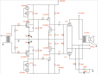
You can also use LL1570 and use this circuit
Attachments
So you say that it would be beter to use an input transformer as a phase spliter?
so i can use LL1676 (1:2+2) and use 6SN7 (half to each phase) and than to the output stage (PPP 2A3) and I will get 1.55Vrms input sensitivity.
or i can use LL1674 (1:4+4) and use 26 (one for each phase) and than to the output stage (PPP 2A3) and I will get 1.87Vrms input sensitivity. (I have a low-Z preamp)
are there any problems with those circuits?
Having a low Z preamp is a good thing when using input transformers. However I am always a little wary of attempting step ups, its far more likely to work with input transformers than IT's, but there are no guarantees. High frequency roll off is what you are possibly going to get.
Shoog
- Status
- Not open for further replies.
- Home
- Amplifiers
- Tubes / Valves
- #40-LL1660-4*2A3