Hi guys,
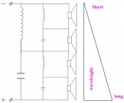
I'm thinking of an easy way to construct 4 way crossover.
1. My question is whether the crossover from the drawing will work normally?
2. Will it behave as a second row crossover for the tweeter?
3. If the answer to Q-No:2 is "NO", Will adding additional capacitor for the tweeter work normally/can it be added without ending in problems with the response?
4. Do you like it?
5. Any other opinion and recommendations are welcome and needed!
Best Regards!
Attachments
Hi,
1. I don't know, more work should be done.
2. I don't know
3. ?
4. Interesting because I like passive crossover techniques, there are a lot work to do in this area. Each day I learn things.
5. Easy doesn't mean correct. A four way is a complex loudspeaker for experiment designers. The crossover could be more complex.
This topology seems complex and needs a lot work to make it work : You should by hand calculate the formula to estimate the components value.
The polarity of the driver must be correctly estimate too, not always the case.
Take a look here :
ARGOS loudspeakers
ARGOS loudspeakers
Regards.
It will "work", but a bit of a nightmare to get to work well as changing one component will affect all the rest. You also have a mix of 1st and 2nd order i believe.
dave
dave
Yes, it will work but as Planet 10 said, it won't be easy. I did exactly the same thing in 2002 for a 4-way I still use today in my 2-channel HT setup, but I eventually broke it into two series crossovers, one for the tweeter and upper midrange (upper half) and the other for the lower midrange and woofer (lower half). Then I treated those as two parts of a combined parallel network with a capacitor feeding the upper half and an inductor feeding the lower half.
Paul
Paul
this article may be of interest: Series vs. Parallel Crossover Networks
I think series xovers are good for simple 1st order 2-ways, but beyond that they aren't worth the hassle (although it's an appealing idea) - it's much easier to predict the outcome of changes in parallel xovers.
I think Tony Gee uses mostly series xovers:
Humble Homemade Hifi
I think series xovers are good for simple 1st order 2-ways, but beyond that they aren't worth the hassle (although it's an appealing idea) - it's much easier to predict the outcome of changes in parallel xovers.
I think Tony Gee uses mostly series xovers:
Humble Homemade Hifi
The problem with using a series crossover (unless it is designed by someone with experience), is that one driver affects the other. They do this via their impedances, which are complex and varied with frequency, in a way which doesn't benefit crossover design but simply "is what it is".
Only two ways to get this to work predictably, IMO. One is to model the drivers and compute the responses, the other is to equalise the impedances and then begin with the textbook crossovers and tweak them until the response is satisfactory.
Only two ways to get this to work predictably, IMO. One is to model the drivers and compute the responses, the other is to equalise the impedances and then begin with the textbook crossovers and tweak them until the response is satisfactory.
Thank you guys!!! You really opened my eyes!
I think that with a certain approach and careful driver choosing this type of crossover is easier opposed to parallel crossovers which don't care that you choose and how you choose it 🙂
In my opinion the main risk with series crossover are the impedance versus frequency curves of both the inductor and the capacitor.
At the crossing frequency they both should be at least:
>or=driver impX2 or >or= imp of driver1+ imp of driver2
For example: both drivers are 8 ohm - 8+8=16, if the capacitor and the inductance are both 8 ohm at that frequency, then the LC formed by them will be 16 ohm as well and two 16 ohm resistances in parallel equal 8 ohm total resistance...
...but signal path through one of the elements and one of the speakers will be with resistance of 16 ohms as well and 16+16 is 8 when talking about crossovers... then 8+16 is 5.33 ohms which is within tolerable for all amplifiers (PARALLEL RESISTOR CALCULATOR)
But if we are dealing with 4 ohm drivers? Then we will end with 2.66 ohm impedance at the crossover point... which is uncool...
So smaller capacitors ans bigger inductances can be considered as a safety rule of thumb...
Question: at what point below the mean level should be the crossover point for first order crossovers? - -3, -6, -9 or -12 - I'm in a doubt between 3 and 6...
But resistance equal to the driver impedance attenuates it with 6 decibels... but with -6 db for both decibels at the crossover point I end up with the 2.33 ohm imp for 4 ohm drivers... - is that normal or is due to untrue suggestions?
Thank you for the answers in advance!
T101
I'm not sure what you are getting at with your impedance references and I don't think it works like that. There is a thread around here somewhere that mentions 1st order series and parallel crossovers using the same values have the same impedance plot.
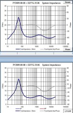
I've attached a impedance plot for series (bottom graph) and parallel (top graph) crossovers using a 6R nom tweeter and a 8R nom woofer using the same inductor and cap values. The plots are identical and the impedance used to create these are the actual (imp/freq plot) and not nominal. When you introduce correction circuits into the filter then the impedance plots do vary but are generally quite close at the crossover point.
First order crossovers are 3dB down at the crossover point. You really need to model in some software using frd and zma files and you get to see what's really happening with the FR and impedance etc if you are interested in how it all looks. Using textbook formulae gives little or no indication on what's really happening. That said, all Andy G's are done without measuring etc but he's very experienced and gets great results.
Have a look around Andy G's site and you will get a better idea of what's possible with 1st order series. I've heard his speakers and they get a big thumbs up and it's through his influence many years ago that made me head over to series crossovers in the first place.
I'm not sure what you are getting at with your impedance references and I don't think it works like that. There is a thread around here somewhere that mentions 1st order series and parallel crossovers using the same values have the same impedance plot.
I've attached a impedance plot for series (bottom graph) and parallel (top graph) crossovers using a 6R nom tweeter and a 8R nom woofer using the same inductor and cap values. The plots are identical and the impedance used to create these are the actual (imp/freq plot) and not nominal. When you introduce correction circuits into the filter then the impedance plots do vary but are generally quite close at the crossover point.
First order crossovers are 3dB down at the crossover point. You really need to model in some software using frd and zma files and you get to see what's really happening with the FR and impedance etc if you are interested in how it all looks. Using textbook formulae gives little or no indication on what's really happening. That said, all Andy G's are done without measuring etc but he's very experienced and gets great results.
Have a look around Andy G's site and you will get a better idea of what's possible with 1st order series. I've heard his speakers and they get a big thumbs up and it's through his influence many years ago that made me head over to series crossovers in the first place.
Attachments
Its an old thread, but..Yes, it will work but as Planet 10 said, it won't be easy. I did exactly the same thing in 2002 for a 4-way I still use today in my 2-channel HT setup, but I eventually broke it into two series crossovers, one for the tweeter and upper midrange (upper half) and the other for the lower midrange and woofer (lower half). Then I treated those as two parts of a combined parallel network with a capacitor feeding the upper half and an inductor feeding the lower half.
Paul
Paul, have you done something with your idea?
I am about to start with same 4-way solution ...156hz, 1500hz, 10000-12000hz....
- Status
- Not open for further replies.
- Home
- Loudspeakers
- Multi-Way
- 4 Way Series Crossover?