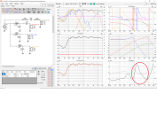
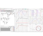
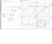
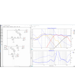
Been simulating both in Vituaxcad and Xsim with my own measured 4 drivers, and made 2 simulations on both programs.
But have used the impedance curves from JBL specs, but DON´t have a impedance curve from the Aga cd working from ca 8-900-9,5 K!
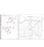
So ignore the impedane markt in red circle on the simulations.
The drivers are Jbl 2235h, Jbl E-145, Jbl 2405h and a 10 kilo compression driver from Swedish Aga/Baltic in a 25 kg diy Jbl 2344a Bi-radial horn.
Xoverpoints are around 200, 900 and 9,5 K.
Can these 4 simulations be trusted, or do the low values of the components fool the program?.
Is one of the simulations preferable to the other, and if so why? (if you remove the financial)
Will all these different simulations sound relatively the same, or can the supposedly "equal simulations" sound very different even if they look alike?
I attached all 4 simulations separate, and one with all 4 in same foto.
Im in trying to learning some more about passive filter mode.
EDIT...Forgotten to tell that 2 are 8 ohms driver, one is 16 ohm and AGA cd is 20 Ohm !
Best regards John
But have used the impedance curves from JBL specs, but DON´t have a impedance curve from the Aga cd working from ca 8-900-9,5 K!
So ignore the impedane markt in red circle on the simulations.
The drivers are Jbl 2235h, Jbl E-145, Jbl 2405h and a 10 kilo compression driver from Swedish Aga/Baltic in a 25 kg diy Jbl 2344a Bi-radial horn.
Xoverpoints are around 200, 900 and 9,5 K.
Can these 4 simulations be trusted, or do the low values of the components fool the program?.
Is one of the simulations preferable to the other, and if so why? (if you remove the financial)
Will all these different simulations sound relatively the same, or can the supposedly "equal simulations" sound very different even if they look alike?
I attached all 4 simulations separate, and one with all 4 in same foto.
Im in trying to learning some more about passive filter mode.
EDIT...Forgotten to tell that 2 are 8 ohms driver, one is 16 ohm and AGA cd is 20 Ohm !
Best regards John
Attachments

Last edited:
There are broad differences that might have an effect, but would do so regardless of the crossover type. Eg the system response being the same when the driver responses are different. What effect specifically are you asking about? Also can you expand on your low value comment, what is low?

Thanks Allen for your response, your knowlege and experience is valuable 👍There are broad differences that might have an effect, but would do so regardless of the crossover type. Eg the system response being the same when the driver responses are different. What effect specifically are you asking about? Also can you expand on your low value comment, what is low?
With "low" i mean for ex caps under 0,8 uF, coils under 0,1 mH in combination with higer values resistors.
I can imagine that there are a lot of "changes" in an electrical composite circuit. because the components' resistance, current and voltage gain, capacitance and other properties are not constant, but can depend on voltage and current. (That we can see)
I also notice that if certain values of components are "above a certain limit", then an increased value (or decreased) of a component elsewhere in the electrical chain makes "no difference" at all.
And that things may happen in the circuit, which we or the simulation program cannot "interpret" or see
And what does a series of LCR-notches create in parallel in the tweeter and midbass circuit, apart from impedance adjustment?
Witch simulation in post #1 would you prefer ?
Fewer parts, cheapest, higher order ?
regards john
Attachments
Yes the values can go out of range of the circuit and become 'insignificant'.
Different circuits can give the same response, sometimes they are just the same. Other times the lower impedance is a concern.
Sometimes you have a second order filter, say a low pass that uses an unusually small inductance. With a high Q, the circuit will draw in more current and increase the response. For this to happen, the impedance falls.
Yes the interaction is complex, but you can see the end effect in the simulator. Look at the separate responses to see you are using the drivers properly. Look at the impedance to see the amplifier can deal with it.And that things may happen in the circuit, which we or the simulation program cannot "interpret" or see
Different circuits can give the same response, sometimes they are just the same. Other times the lower impedance is a concern.
Sometimes you have a second order filter, say a low pass that uses an unusually small inductance. With a high Q, the circuit will draw in more current and increase the response. For this to happen, the impedance falls.
It's easy to point in the right direction and then to experiment... but to give a straight answer here would take more study, perhaps looking at polar plots. Working off responses as you are here is fine if you have an understanding of the behaviour of the drivers and cabinet.Witch simulation in post #1 would you prefer ?
Fewer parts, cheapest, higher order ?
Too steep and too shallow can both be a problem in some situations. You also have to fit in with the basic needs, such as avoiding cone breakup.
Thanks again Allen!
In my case with 2 pieces of 8 ohm drivers, one 16 and one 20, the sensitivity is 107-109 dB/1W on both Aga cd and Jbl 2405h, while Jbl 2235h and jbl E-145 are 93 and 98 dB respectively /1W.
And i wont to use my reseiver/amp (Onkyo NR747) to the best.
so it would be ideal if the Jbl 2235h & E-145 were around 3.5 ohms in the simulation, while the Aga cd & Jbl 2405h were around 10 ohms.
Because in practice it would mean that the Jb 2235h & E-145 take more % of current available from the receiver?
Say if you have 100 watts/8 ohms, maybe 2235 & E145 take 70% of the total effects, i.e. around 70 watts.
Or am I thinking wrong?
And I really like to know which filter you dislike least, or would prefer in my first post 😉.
Regards John
I also found that i can Bi-amp from Onkyo 747, and maby better to connect 2235h and E145 from output "Front" and AGA and 2405h from "BACK or HEIGHT terminals".
But have doubt if it would be better, or if its just a PR thing from Onkyo>!
https://www.onkyo.com/manual/txnr747/adv/en/044.html
But have doubt if it would be better, or if its just a PR thing from Onkyo>!
https://www.onkyo.com/manual/txnr747/adv/en/044.html
Why do you say you want them to be this impedance?so it would be ideal if the Jbl 2235h & E-145 were around 3.5 ohms in the simulation, while the Aga cd & Jbl 2405h were around 10 ohms.
Why do you say you want them to be this impedance?
Sorry for the late reply Allen, I have spent the last 3 days trying to build an impedance jig so that I can measure my existing drivers & in the future benefit from this knowledge.
I figured that the output power is less at 8 ohms than at 4 ohms, and maby the 2235h and E-145 can "suck more avalible power" from the amp if its around 3-4 ohm!
Have read that In the vast majority of cases, the output power is less at 8 ohms than at 4 ohms and that it is a consequence of the fact that the amplifier does not primarily deliver a power but a voltage and that in normal HiFi amplifiers this is constant and essentially independent of the value of the impedance. Therefore, when the impedance is made smaller, the current will increase and consequently the output power will also increase. voltage.
As an example with a 100W amplifier
100W in 4 ohms = 5A, 20V (rms) which means that 35V should be enough as a supply.
100W in 8 ohms = 3.5A, 28V (rms) which means that at least 45V supply is required.
Wrong thinking by me or?
Regards John
I looked up these drivers and they appear to be 8 ohms. How do you plan to make them 4 ohms?
Hahaha, that i cant do Allen ( but sometimes i wish)....
But doesen´t the amp "leave" more "watt" in "that region", if i build a passive xover that goes from 3-4 ohm from 20-1K (bottom) and raise it slowly up to 10-12 ohm at the "end"?
Elektrical circuits are complicated to say the least
John
- Home
- Loudspeakers
- Multi-Way
- 4 quite different passive 4-way xover with almost the same outcome possible?