Hi guys!
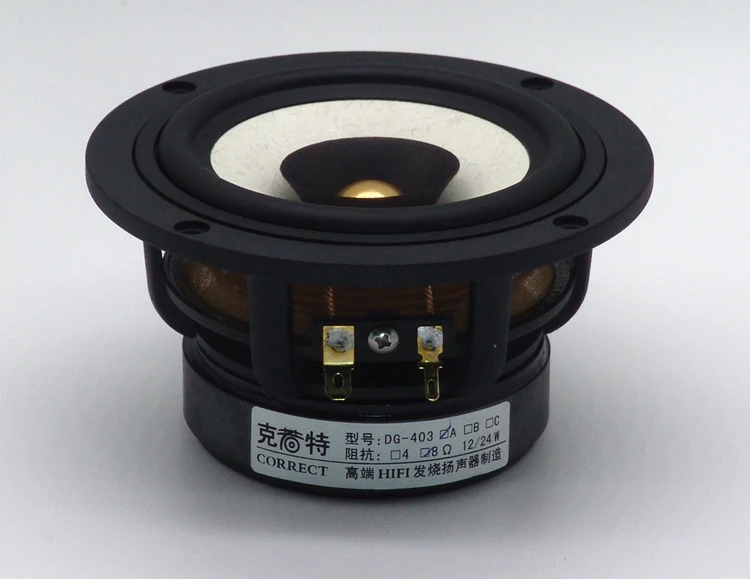
I'm totatlly new in this field, I have done some research to learn the best cabinet I would build for my pair of chinese speaker 4" Aucharm DG-403 (1PCS 2019 New Aucharm 4'' DG 403 Full Range Speaker Driver Casting Aluminum Frame IIR Surrouding Mixed Paper Cone 4/8ohm 25W|Speaker Accessories| - AliExpress) which doesn't have many technical information on the store . So far, I found the TL more interesting, locazating the speaker 1/3 of the legth of the tunel to avoid the dip. So I used python to calculate dimensions given a design that I liked. According to the store the Fs is 72hz, so I end up with these two cabinets, the left tunned to 72hz and the right tunned to 50hz. I got a TDA7377 amplifier and a preamp with ES9018 decoder DAC with 12AU7 tube used probably for buffering. Every sigle piece of this system I found doing researches on youtube and forums, I'm completaly new in this field, therefore, I would appreciate so much any suggestion.


Cheers from Brazil.
I'm totatlly new in this field, I have done some research to learn the best cabinet I would build for my pair of chinese speaker 4" Aucharm DG-403 (1PCS 2019 New Aucharm 4'' DG 403 Full Range Speaker Driver Casting Aluminum Frame IIR Surrouding Mixed Paper Cone 4/8ohm 25W|Speaker Accessories| - AliExpress) which doesn't have many technical information on the store . So far, I found the TL more interesting, locazating the speaker 1/3 of the legth of the tunel to avoid the dip. So I used python to calculate dimensions given a design that I liked. According to the store the Fs is 72hz, so I end up with these two cabinets, the left tunned to 72hz and the right tunned to 50hz. I got a TDA7377 amplifier and a preamp with ES9018 decoder DAC with 12AU7 tube used probably for buffering. Every sigle piece of this system I found doing researches on youtube and forums, I'm completaly new in this field, therefore, I would appreciate so much any suggestion.
Cheers from Brazil.
Last edited by a moderator:
Greets!
Just a quick response for now: to tune a TL, it must be < a 1/4 WL of the desired frequency [Fp] due to its pipe end correction, so will be at least 0.613*effective radius.
Just a quick response for now: to tune a TL, it must be < a 1/4 WL of the desired frequency [Fp] due to its pipe end correction, so will be at least 0.613*effective radius.
Last edited:
Did you model the lines?
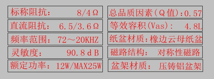
Let’s assume Fs = 72 Hz, these are given Qt = 0.59, Vas = 4.8 litre.
dave
Let’s assume Fs = 72 Hz, these are given Qt = 0.59, Vas = 4.8 litre.
dave
Yes I calculated 1/4 WL and used the Sd of 75,42cm2, assuming the value 97-98 is de diameter of the surface area of the cone. I didn't use any othe parameters, should I use?
Thank you everyone!
Thank you everyone!
Last edited:
used the Sd of 75,42cm2
Sd has little to nothing to do with designing a TL. It implies you ar eusing Classic Design Techniques to design your line, Rarely optimal, usually mediocre or worse.
dave
Ok, thanks.
So I can't model my TL with the parameters they give, so should I just follow their recommendations?
So I can't model my TL with the parameters they give, so should I just follow their recommendations?
You only need Fs, Qt and V as to model a TL. Some use BL but that can be derived.
You have all of those.
dave
You have all of those.
dave
Qo = Qt= 0.57
Thanks! From dim memory remember using this, though also remembered it was closer to Qes based on ?? [don't remember, maybe Thorsten L.?], so did some 'close enough' calcs using the attached and HR impedance plots.
At these two extremes of 20 Hz/0.21 Qes/0.2 Qts & 49.6 Hz/0.78 Qes/0.71 Qts it comes closest to [Qes*Qts]^0.5, so in some cases will make the cabs a bit too small, though with the recommended 0.5 ohm min. series resistance [Rs] for wiring, etc., handles the difference in both cases.
I've never found a definitive for Qo, but from the Fostex site, it appears they use it as a ~equivalent for Qt, and from a (very) brief glance, it seems like it was in this, dated '86 also: https://pure.tue.nl/ws/files/3397667/240847.pdf
Quite possible it differed elsewhere though, but I suspect in most cases treating it like Qt will be 'good enough', especially with tolerances etc.
Quite possible it differed elsewhere though, but I suspect in most cases treating it like Qt will be 'good enough', especially with tolerances etc.
Falls in line with my understanding and calculating per the chart for a 0.403 max flat Qts, 0.43 Qes [ignoring [Rs] and with a ~1.01% error due to having to approximate F1, F2 in HR, Qo = 0.4133:
[0.43*0.403]^0.5 = 0.4163 mean or ~6.7% closer to Qes than Qts, so typically use it and 0.5 ohms to insure an adequately large net volume [Vb].
That said, early on, way before I was exposed to Qo, someone or something told me I should be using a 1/2 octave [0.7071x] on each side of Fo for F1, F2 [1.0 octave bandwidth [BW]], which equates to a simpler to calculate 0.4052, so in this scenario it is indeed Qo = Qts to all but the 'x' number of decimal points perfectionist.
Regardless, the Qo math is > Qts, though < Qes, so Qo = Qts is good enough overall if no measured impedance plot is available and use Qes if wanting a little extra 'cushion' of air in the box [Vb].
... Qo, but from the Fostex site, it appears they use it as a ~equivalent for Qt
Mark has also used it for Qt.
dave
OK, now that we've 'hammered' Qo down to = Qts, back to our regularly scheduled program 😉
Converting your TL designs to HR is a bit too tedious for me ATM, so just going to remark that it looks like one size pipe from the closed end, then a stepped transition to a larger pipe [driver chamber], then back down to the original size to its terminus [vent], a design I don't recall ever seeing and while I'm pretty sure I can sim it in HR, haven't figured it out yet, so no clue if there's any audible advantage to it versus [Vs] just making it the same cross sectional area [CSA] its full length [basic TL].
As a general rule [ROT] then, the pipe needs to have a minimum [min.] volume [Vb] of ~ 4x Vas up to ~10x Vas depending on how small the Vas spec is and how much LF gain BW one wants, so CSA will normally be considerably > Bailey's [Sd] requirement for optimal response.
FWIW, for optimal driver TL loading a compression ratio of [Sd]/2 = 2:1 for optimal vented alignment driver specs.
WRT TL path-length, we need to account for the aforementioned pipe's end correction and the stuffing's impact on effective acoustical path-length, so another ROT is desired tuning [Fp]*0.81x for typical damping and 0.707x for max damping with the understanding that at some density [Fp] will begin moving back towards its higher empty pipe [Fp].
All that said, while any taper pipe can be used regardless of its Qts', for drivers with a < ~0.403 Qts' = constant taper [straight TL] and as it moves towards a lower Qts' it ideally needs to be inverse tapered [TQWT] and increasingly expanding [also technically a TQWT, but prefer to describe it as a horn], so with the DG-403's 0.57 + any added series resistance [Rs] it ideally 'wants' a bit of horn loading to offset its relatively 'weak' motor.
For the most accurate alignments based on full T/S specs, MJK's Classic Alignment Tables:
https://web.archive.org/web/20130328134100/http://www.quarter-wave.com/TLs/Alignment_Tables.pdf
Excel worksheet download: http://web.archive.org/web/20120304...om/TLs/Alignment_Tables_Calculator_3_3_09.xls
Qts': Qts + any added series resistance [Rs]: Calculate new Qts with Series Resistor


So I designed a TL Sl/So = 0.5, tunning to 50Hz. But I think the speaker is too close to the wood behind, there is any problem?
Last edited by a moderator:
How I calculate the parameters Le and Xmax?
You have to measure them.
- Home
- Loudspeakers
- Full Range
- 4" Full Range Transmission Line - Aucharm speakers