Don't panic!
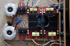
Just in case anyone thought my sofa had eaten me, I am still alive and can post a few photos and a bit of a progress up date. Work has been very busy recently, so I've not had a huge amount of time to progress this little project and I have only recently aquired a copy of AutoCAD to draw up the design for my amp cases (which are going to be machined and engraved). Anyway, in the mean time I have at least managed to listen to plenty of music and it has performed flawlessly, so it definately deserves a good home... I'm sure you'll agree that the current arrangements are a little "sheltered housing" rather than footballers mansion! LOL 😀
Just in case anyone thought my sofa had eaten me, I am still alive and can post a few photos and a bit of a progress up date. Work has been very busy recently, so I've not had a huge amount of time to progress this little project and I have only recently aquired a copy of AutoCAD to draw up the design for my amp cases (which are going to be machined and engraved). Anyway, in the mean time I have at least managed to listen to plenty of music and it has performed flawlessly, so it definately deserves a good home... I'm sure you'll agree that the current arrangements are a little "sheltered housing" rather than footballers mansion! LOL 😀
Attachments
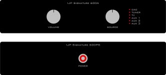
This is what I am hoping the fronts will look like when I have them ordered. The top one is the actual amp itself and the bottom one the power supply. The source switch I have at the moment has 4 poles with 6 positions and currently signals and grounds are all separately switched. Going forwards I am going to combine the Left and Right signal grounds (as it is pretty pointless them being separate anyway) and use the fourth pole for driving the LEDs which indicated which source is selected, which should be a neat and easy way of doing things. Hopefully that will look the business when its done.
The power supply power switch is likely to be a vandal proof jobbie from RS Components, though I am struggling one to handle the current and give me the lit red ring. I might have to go with a push to make with a relay for power up and perhaps use a soft start circuit. Anyway, lots to think about!
The power supply power switch is likely to be a vandal proof jobbie from RS Components, though I am struggling one to handle the current and give me the lit red ring. I might have to go with a push to make with a relay for power up and perhaps use a soft start circuit. Anyway, lots to think about!
Attachments
Very nice build, Ian. Congratulations!
I'm not so sure using the fan wouldn't be noisy, but I may be wrong.
Some questions:
1) Where did you get the amplifier boards and the supply boards? They seem to resemble some I found on eBay, but I am not sure which they might be.
2) Do smd parts come pre-assembled? I am not too sure I can handle that quantity of smd parts myself and not blew thing up.
3) What are you using as bridging/ balancing stage?
Congrats again.
Carlos
Hi Carlos,
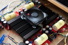
The fan is a little noisy when close up, but it is only running at about 4.5V (as opposed to the 12V it would normally operate at). Plus, this is only for testing, the case I am ordering will be fine with passive cooling.
1) It was a Group Buy from right here from DIYAudio organised buy Peranders 🙂
2) No, I had to solder the SMD parts on myself, which was a bit of a learning curve. It can be done with patience.
3) I am running the boards in parallel at the moment, so they are bi-amping my speakers at the moment. One of the things I want to do with this amp are to make it flexible and allow for use in bridged mode, with an active crossover, etc.
Thanks for the kind words.
Ian
- Status
- Not open for further replies.