Having been the proud owner of a chipamp for a few years now, I have decided to delve in a little deeper than before. My current amp is a LM3886 based design using the BrianGT kit and it has done well thus far. For those that are interested, there is a construction diary here:
http://www.diyaudio.com/forums/chip-amps/92673-yet-another-3886-gain-clone.html
However, whilst browsing away one day I came across the BPA300 thread and then the group buy for the boards with SMD components. This was early last year and through one reason and another I haven't gotten round to doing anything with them. A friend of mine was recently on the search for speakers and then decided he needed a new amp to go with it and this gave me the opportunity to pass my old amp on to him (albeit modified) and start afresh.
So this thread is going to be dedicated to the construction of my new amp, which will be based around the 4 PA150 boards, allowing me to bi-amp my Amish 45/97s. Also, there will be the off aside as I modify my old amp for my friend, as he has a special requirement in that it needs a summed mono output for his sub-woofer.
Back to the main event and the overall design will a two box amp, however, it is not going to be a pre-power set up, like my current arrangement, which makes use of an buffered preamp:
http://www.diyaudio.com/forums/solid-state/121399-opa627-buffer-based-preamp.html
This will be an integrated amp, with the 4 amp boards, pre-amp, volume and source selector all in one box and the power supplies for the various sections in another box. The idea being to separate the noisy circuits from the less noisy ones, very much along the Naim philosophy, to name but one. 😀
So my order from RS arrived today with pretty much everything I need bar a couple of power connectors for the multicore umbilical cord that will connect the power supply to the amp. I am pretty much decided on the case from Hifi2000, but haven't determined the layout I want to use or what I want etching / machining on the front, so that may cause a hold up... that and having to do some repairs to my en-suite 🙁
In the first instance I am going to be recycling the power supplies from my exisiting amps (a 225VA tranny and associated parts have been procured for my friends amp) with the intention that I can easily upgrade that box in future without having to disturb the amp itself. Its a good starting point as it'll contain 2 x 300VA transformers with rectifier boards and a regulated 15V power supply for the buffer circuit. Shine7 who built the BPA300 monoblocks on his website went for massive power supply capacitors, but I seem to recall that these chips don't require huge amounts of storage, in fact if you look at the aclaimed Peter Daniels amps, they have very little. I think a bit more research or experimentation may be required when I get to that stage.
Anyway, enough for now, photos of bits to follow! 🙂
Oh, actually... this is the case I am thinking of in black 2U with the 10mm front and 3mm top and bottom:
modushop.biz
modu
And this is the inspiration:
DIY BPA300 6x LM3886 300W audio Amplifier
There are a few other considerations that I might give to this amp as well including the lightspeed style attenuator or possibly a remote control feature, maybe both. I am hoping that I can retain flexibility in the design such that upgrades / modifications are easy to implement. Lets face it there is a lot to experiment with, valve buffers discrete op-amp replacements, bridging and electric crossovers!
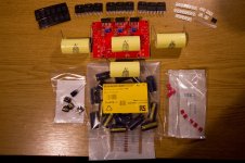
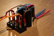
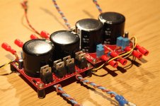
As promised a snapshot of the parts, not all, but the main bits. The strips to the top righthand side are the SMD components, which I am really looking foward to soldering! 🙄
Also fun to fit to the boards are the input caps, which are huge!! Guess that means I can do away with the cheap electrolytics that I currently use for DC blocking. 🙂
Also fun to fit to the boards are the input caps, which are huge!! Guess that means I can do away with the cheap electrolytics that I currently use for DC blocking. 🙂
Attachments
Lots of soldering
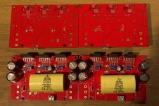
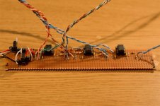
So I spent some time the other night and today oldering the components to the boards, which mostly went well, however there were a couple of challenges. The most frustrating was that a few of the square pads didn't want to take the solder which is clearly not good, however, I got there in the end.
The second was working with SMD components, which are easy to lose, as I found out after a resistor went shooting off out of the tweezers I was using never to be seen again. I'll be making a small RS order by the looks of it to get some replacements, good job 5 is the minimum order. What I should have perhaps done before I started the SMDs was looked to see if anyone had done a guide, as I struggled through 2 of the boards before figuring out my workflow. I'll share my findings:
This has the advantage that the components should sit flush with the board and you can position them neatly. I found it efficient to do a few components down one side, then turned the board around to solder the other side.
One ommisson you'll see on the boards at the moment are the output resistors, this is so I can set the offset of each chip before they are all linked together. At some point I need to set all my trim pots to a central position.
I also need to find somewhere that stocks terminal blocks for the power and speaker connections with 9.5mm spacing, so if anyone can point me in the right direction or propose an alternative I would be greatful.
So I spent some time the other night and today oldering the components to the boards, which mostly went well, however there were a couple of challenges. The most frustrating was that a few of the square pads didn't want to take the solder which is clearly not good, however, I got there in the end.
The second was working with SMD components, which are easy to lose, as I found out after a resistor went shooting off out of the tweezers I was using never to be seen again. I'll be making a small RS order by the looks of it to get some replacements, good job 5 is the minimum order. What I should have perhaps done before I started the SMDs was looked to see if anyone had done a guide, as I struggled through 2 of the boards before figuring out my workflow. I'll share my findings:
- Tin one pad
- With the component in the tweezers move it close to the pad
- Then heat the pad and move the component into place
- Remove the soldering iron and keep the tweezers steady
- When the solder is set then remove the tweezers and you can solder the other side
This has the advantage that the components should sit flush with the board and you can position them neatly. I found it efficient to do a few components down one side, then turned the board around to solder the other side.
One ommisson you'll see on the boards at the moment are the output resistors, this is so I can set the offset of each chip before they are all linked together. At some point I need to set all my trim pots to a central position.
I also need to find somewhere that stocks terminal blocks for the power and speaker connections with 9.5mm spacing, so if anyone can point me in the right direction or propose an alternative I would be greatful.
Attachments
Slow but steady
Its been a little while since I have updated this thread, mostly because not very much has progressed in the last couple of weeks thanks to needing to do some other more pressing DIY jobs, like fixing my shower.
Anyway, as I said earlier there will be a couple of builds in this thread and at the moment that one that I have been progressing with is the front end circuitry for my friend's amp. This is a going to be a buffered chip amp using the LM3886 boards I already have, but with a mono sum output for a sub.
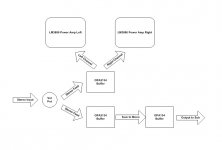
I have now completed (fingers crossed) the board that will drive the front end, which is based around an OPA2134 to drive the chipamp boards, then a combination of a OPA2134 and OPA134 to created the mono sum. I decided that I would use the 2134 to act as a buffer and prevent crosstalk between the channels, then combine them and drive the mono output using the 134. A block diagram attached illustrates the layout.
I have not tested this yet as I need to sort out the front end power supply. But basically this circuit will take a feed from the power supply for the chipamp boards and then regulate the voltage down to +/-15V to to power the op-amps. I've knocked up the regulator and op-amp circuits on some breadboard.
Its been a little while since I have updated this thread, mostly because not very much has progressed in the last couple of weeks thanks to needing to do some other more pressing DIY jobs, like fixing my shower.
Anyway, as I said earlier there will be a couple of builds in this thread and at the moment that one that I have been progressing with is the front end circuitry for my friend's amp. This is a going to be a buffered chip amp using the LM3886 boards I already have, but with a mono sum output for a sub.
I have now completed (fingers crossed) the board that will drive the front end, which is based around an OPA2134 to drive the chipamp boards, then a combination of a OPA2134 and OPA134 to created the mono sum. I decided that I would use the 2134 to act as a buffer and prevent crosstalk between the channels, then combine them and drive the mono output using the 134. A block diagram attached illustrates the layout.
I have not tested this yet as I need to sort out the front end power supply. But basically this circuit will take a feed from the power supply for the chipamp boards and then regulate the voltage down to +/-15V to to power the op-amps. I've knocked up the regulator and op-amp circuits on some breadboard.
Attachments
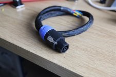
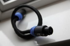
Right, still far too many things going on for me to have made much progress with this, however, I have decided on and gotten the power connectors to link the box that will contain the power supply to the box that will contain the amp. A number of factors affected the choice, but in the end it came down to availability. The choice is the 8 pole speakon connector which gives me 8 connections all rated at 30A at 250V, which should be more than sufficient for what I require. What this will allow me to do is use 3 poles for the regulated feed for any preamp circuitry, then 5 Poles for the dual power supply for the amp boards, by using a common 0v rail.
The connectors are fairly substantial and now I need to decide how I am going to wire them to keep the low voltage low current away from the higher voltage high current lines. Perhaps it isn't really necessary?
I haven't ordered the case yet either as I need to decide how I want the front to look and if I want it engraving or lettering, the latter most likely. Also, I have been on the search for a suitable power switch and the one that I like was typically out of stock and was also £25!
Yikes, 17 days since the last update... how very poor!
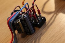
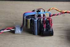
So, what has happened since the last update? Umm, not much. I have gotten around to progressing the power supply that will power my friend's amp, which will also be used for testing the PA150 boards. Twin bridge rectifiers feeding two 4700uF caps with 1000uF as bypasses. I need to add a couple of resistors to drain the caps when the power is turned off.
So, what has happened since the last update? Umm, not much. I have gotten around to progressing the power supply that will power my friend's amp, which will also be used for testing the PA150 boards. Twin bridge rectifiers feeding two 4700uF caps with 1000uF as bypasses. I need to add a couple of resistors to drain the caps when the power is turned off.
Attachments
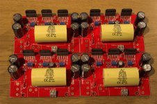
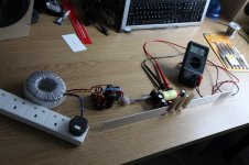
Yay, I have made some more progress! I finally found some terminal blocks for the boards. After searching for ages for something with a 10mm pitch (as per the instructions) I figured out that they are actually 9.52mm pitch and got just what I needed from RS. With having the power supply for my friend's amp built, I decided I would try one of the boards and check it was working. All went to plan and I adjusted the little trim pots until I had a matching 15.0mV offset on all three chips. So now I need to do the same with the other three boards and then install the output resistors before I can get some speakers attached and try them properly!
Best get thinking about ordering the case ASAP!!
Best get thinking about ordering the case ASAP!!
We have music
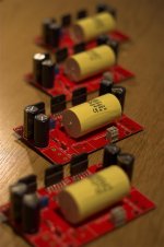
OK, so all four boards have no been tested and all set to 15mV DC offset, meaning I could install the Dale output resistors. So far so good and when I fired them up again, everything seemed to be working fine, a combined offset of about 16mV on all of the boards. At this point I was feeling pretty confident, so hooked up a little pair of speakers that came with a 4.1 surround system for my computer. We have a result! I then decided to up the ante and attached a pair of bookshelf speakers I am experimenting with.
The music flowed and it sounded great! I am really impressed with these boards so far. 😀
Since i don't have a case I had to use some strip aluminium to act as a temporary heatsink, which did an ok job, but the chips get pretty frickin warm. Am super excited about getting this thing built now.
Attachments

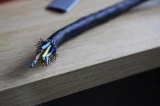
Since I am still short of a case I decided I'd progress some of the other items I need to be doing, such as creating the umblilical cord that will attach the power supply to the amps. This will need to carry power for the four amp boards and the pre-amp section. As previously discussed I bought the 8 way Speakon connectors for this purpose, which will allow me to use two independant supplies for the amp boards and a further supply for the pre-amp section.
I have braided some 1.5mm2 copper mains wiring together then cut it to form three lenths, so 9 conductors in total. Two will be doubled up to form the 0V connection. The three bundles were twisted together, then covered in plastic cable sleeve and which were tidied up with some heatshrink. Wiring into the plugs was fairly straightforward and, it was only on the second one that I had managed to make six of the connections before I reallised I had forgotten to slide on the cable clamp! DOH Thankfully they are screw terminals, otherwise I might have gotten angry.
Anyway, I think the result is rather tidy and having checked that all the connections match up with my meter it should hopefully work like a charm.
I have braided some 1.5mm2 copper mains wiring together then cut it to form three lenths, so 9 conductors in total. Two will be doubled up to form the 0V connection. The three bundles were twisted together, then covered in plastic cable sleeve and which were tidied up with some heatshrink. Wiring into the plugs was fairly straightforward and, it was only on the second one that I had managed to make six of the connections before I reallised I had forgotten to slide on the cable clamp! DOH
Thankfully they are screw terminals, otherwise I might have gotten angry. Anyway, I think the result is rather tidy and having checked that all the connections match up with my meter it should hopefully work like a charm.
Attachments
Nice work and pics. I just ordered some OPA2134 for the preamp section of my Cambridge. I like it quite a bit and do not want to change it much at all, it has the NE5532. Maybe not much of an upgrade and that's OK.
How would you describe the OPA2134?
How would you describe the OPA2134?
To be honest I haven't spent a lot of time listening to them, I used them to test my existing pre-amp when I thought I had destroyed a pair of OPA628s. I chose them as they were good value for money and seem to get good ratings therefore other would be suitable for my friend's needs.
I'm running 4627s in my pre-amp now and they are amazingly good, but I am not sure if they do them as a dual package.
As for whether you should change them in you Cambridge, if it is a socket that makes it easy and you might as well try them. Some people here will tell you that they are good, some bad and others, that the circuit may not be optimal to use a different opamp. If it is easy to do, give it a go, they are fairly cheap at the end of the day.
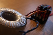
Regarding the power supply I built, that has now been transfered into the case with my existing 3886 setup, putting me one step closer to completing that side of the project for my friend. This means the transformers and rectifier boards have been liberated from the old amp and can be used to test the PA150 boards in anger.
However, the pre-amp section I made for my friend's amp seems to have an issue with the regulated power supply, so I need to do some more work on that.
However, the pre-amp section I made for my friend's amp seems to have an issue with the regulated power supply, so I need to do some more work on that.
Power supply
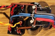
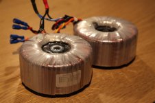
OK, so here are the two 300VA (2x22V) transformers that are going to power the four PA150 boards to begin with, along with the rectifiers and smoothing caps. These have been taken from the old amp. 😀
OK, so here are the two 300VA (2x22V) transformers that are going to power the four PA150 boards to begin with, along with the rectifiers and smoothing caps. These have been taken from the old amp. 😀
Attachments
Bored whilst waiting for a case!
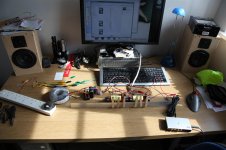
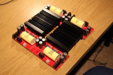
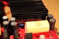
Also, whilst I am waiting for my case I was keen to test the amp boards some more, but needed a better form of heatsink than the aluminium strip I was using previously. I remebered that I had picked up a couple of heatsinks for a project from years back and they have been gathering dust in the loft. So these have been recovered and they are a nice fit for these boards. Hopefully they'll do the job and I can always fan cool with these if I need to.
You'll notice that I have taken a slightly unorthadox approach to attaching the chips to the heatsink and used cable ties. I am confident that these will do the trick for now and something slightly more sophisticated will be used in the final design. 😛
Attachments
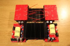
So I have mounted the boards as shown below on a sheet of chipboard and wired it up to my transformers and rectifier boards (as shown in post #17) and connected it to the preamp and speakers that are in my main system, the amps were wired to bi-amp my speakers.... and I got muffled music... oh balls! 😕
I went over all of the wiring a couple of times, then decided to try just one amp and one speaker, which was all good, so try again... ahh, the DOH moment! I managed on both of the tweeter connections to get the cable under the terminal block apature, thus no connection 😱
With that resolved, I got music... sweet beautiful music. Am just auditioning with India Arie, as I know the cd well and it is fabulous, crystal clear highs and nice tight, but extended bass. Suddenly all the effort and time is paying off!
Just to note, these amps seem to run quite hot even with no signal, at least compared with the single chip version (there are now 6 times more of them), so I have a fan mounted on top of the two heat sinks just to move a bit of air and stop them going thermonuclear on me 😀
- Status
- Not open for further replies.
- Home
- Amplifiers
- Chip Amps
- 4 Channel PA150 Construction Diary