I have designed most of my per-amplifier, including the inputs.
All I need now it a way to use buttons to select input.
I have taken a look at the push button in hope that it could be used
But I have not been able to find a way to make 4 alternating latching buttons or a way for the interface to "remember" wish was pushed last time.
The way I have build my pre-amp, do that I can ignore how the circuit will effect the sound.
I have a 5V-10V DC input and want to go trough to output 1,2,3 or 4, It would be fantastic if an LED could be lit over each button that are selected.
To me do it look like a big project to use push buttons.
How did you solve it, besides using a turn-selector?
Buttons...
There are discrete logic solutions (which is about my level 😉) and using a PIC which I haven't a clue how to do from scratch... although that is what is used in my amp despite it also having a rotary input selector. I wanted full remote control...
Discrete logic can be simple and can be kept alive with a supercap or backup battery to retain settings. In the past I used a CMOS 4017 clocked at a low frequency and used a button array to enable the count and then stop the count when it clocked around to that line on the 4017.
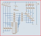
This is a circuit someone on the forum presented (was it 'Lineup?) many years ago. I haven't tried it but it has that 'it will work' look to it. It uses a cheapo CMOS logic chip.
That would be easy to back up with a super cap. The FET interface means no current is drawn in a static state.
There are discrete logic solutions (which is about my level 😉) and using a PIC which I haven't a clue how to do from scratch... although that is what is used in my amp despite it also having a rotary input selector. I wanted full remote control...
Discrete logic can be simple and can be kept alive with a supercap or backup battery to retain settings. In the past I used a CMOS 4017 clocked at a low frequency and used a button array to enable the count and then stop the count when it clocked around to that line on the 4017.
This is a circuit someone on the forum presented (was it 'Lineup?) many years ago. I haven't tried it but it has that 'it will work' look to it. It uses a cheapo CMOS logic chip.
That would be easy to back up with a super cap. The FET interface means no current is drawn in a static state.
Attachments
Arduino is the easy way. Programming for a momentary contact switch (not latching) is about as simple as it gets. If you want it to remember the last setting then you need to write to eeprom on shutdown. If not, make sure it defaults to your most popular source.
I bet it's a long time since latching buttons were used in a commercial hifi. The switches were mechanically linked so pressing one released the previous switch.
You could try salvaging such a switch from old equipment.
I bet it's a long time since latching buttons were used in a commercial hifi. The switches were mechanically linked so pressing one released the previous switch.
You could try salvaging such a switch from old equipment.
Use a 4017 counter. Check my first post here: 4017 | Search Results | theslowdiyer
EDIT: Ah, sorry - multiple buttons to select! Another vote for an Arduino then
EDIT: Ah, sorry - multiple buttons to select! Another vote for an Arduino then
Last edited:
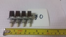
If you do not need electronic/remote control then look for 4 sections ISOSTAT depend switches module on eB - many of them stil to have from UK. Almost half century ago when I started electronic hobby and Intel 8080 8bit mcu was the the last cry of technology, Isostat was state of the art in hi-fi audio. You push a button and release mechanically the switch that was latched before. If you get bigger module, no problem - you can remove the redundant switch from the module easily. And if you manage to get 4pole, you can switch the two channels + the signal LED as well. Almost got sentimental just remembering this part...;-)
Attachments
I used a cmos D-type flip-flop. Again, it doesn't remember the last selection, but as Mooly said a battery or supercap can take care of that. I found I had to be careful with decoupling and add a little delay on the clock line to allow for input settling, but I like the way it works, momentary contact switches, I wanted it to feel like a Quad 44 preamp.
You are all great!
Mooly that schematic looks really great, wondering if there are any chip with a Non-volatile memory.
The solution with the Arduino, I know what I am saying now may be totally idiotic, but I feel that the Arduino solution is like if a woodworker do uses CNC to make his project.
With a CNC, a woodworker can program the computer to perfection, ask the machine to cut every piece out, while the woodworker take a cup of coffee. Without the CNC did the woodworker had to use his skills to saw, file, drill and all that, to end up with a maybe less perfect project, but now is it the woodworker who have made it and not a program.
Its the same with the Arduin, I do "just" ask the computer to make it for me instead of mee having to build it myself. 🙂
MBA that is a super simple method, maybe the best.
But it sounds like none of you use buttons anymore?
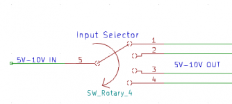
I have a balance control, volume control and an input selector. In other word would it be three turn buttons. I did think that it would look more nice with two turn buttons and a row of input button in the center.
To make it easy to explain my goal, have I drawn a simple turn selector schematic. Sorry that my English is not good enough to explain my intentions.
Mooly that schematic looks really great, wondering if there are any chip with a Non-volatile memory.
The solution with the Arduino, I know what I am saying now may be totally idiotic, but I feel that the Arduino solution is like if a woodworker do uses CNC to make his project.
With a CNC, a woodworker can program the computer to perfection, ask the machine to cut every piece out, while the woodworker take a cup of coffee. Without the CNC did the woodworker had to use his skills to saw, file, drill and all that, to end up with a maybe less perfect project, but now is it the woodworker who have made it and not a program.
Its the same with the Arduin, I do "just" ask the computer to make it for me instead of mee having to build it myself. 🙂
MBA that is a super simple method, maybe the best.
But it sounds like none of you use buttons anymore?
I have a balance control, volume control and an input selector. In other word would it be three turn buttons. I did think that it would look more nice with two turn buttons and a row of input button in the center.
To make it easy to explain my goal, have I drawn a simple turn selector schematic. Sorry that my English is not good enough to explain my intentions.
Attachments
Maybe you can utilize this module to select preamp source input
4 canales WiFi momentaneo Inching rele Modulo de interruptor de bloqueo automatico Modulo de interruptor de rele WiFi Smart Home Control remoto, CC 7 32V|Control remoto inteligente| | - AliExpress
MHCOZY 4CH WiFi RF Wireless Switch Relay, Inching Self-Locking Interlock Mode, for Access Control Smart Garage Door, Compatible with Alexa Goolge Home - - Amazon.com
But it sounds like none of you use buttons anymore?
I have a balance control, volume control and an input selector. In other word would it be three turn buttons. I did think that it would look more nice with two turn buttons and a row of input button in the center.
To make it easy to explain my goal, have I drawn a simple turn selector schematic. Sorry that my English is not good enough to explain my intentions.
Oh, you want a rotary switch.
You are all great!
Mooly that schematic looks really great, wondering if there are any chip with a Non-volatile memory.
All you would need for that circuit to retain its 'memory' would be to add a diode and supercap to the 5 volt supply to the chip. A 47 ohm series resistor would be good practice.
Attachments
Mooly, do I read it correct if I think that the 5V out is R1 to R4?
Do you know how long time a supercap can power that circuit per 1F?
Would that supercap not also power everything going after the voltage out?
Do you know how long time a supercap can power that circuit per 1F?
Would that supercap not also power everything going after the voltage out?
R1 to R4 are just pull down resistors that tie the logic inputs to ground... although I have just spotted something. One of the outputs (whichever is selected) will be high and so that 5 volts (less a diode drop) will appear across one of the 100k resistors. So that is a source of current draw.
Lets say 4.5 volts at 100k = 45uA.
We could probably make the resistors much larger, 1meg or even higher.
1meg would give about 7 to 10 days from a 1F cap, maybe more because the logic will keep latched down to very low voltage levels. The chip itself draws no measurable current when static.
The diode I added means only the chip and parts connected to it are powered, nothing else.
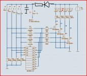
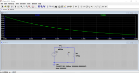
This shows a 1F cap discharging into 1meg. The chip would probably become unreliable at around 2 volts or less (could forget its logic state).
The scale is in seconds and approx 600,000 seconds equal one week.
The other option that I have used is to replace the supercap with a very tiny 3.6 volt nicad backup battery. That would need the diode and resistor rearranging.
If we went to 10 meg with the resistors then the time increases massively and now even diode leakage plays a big part.
Attachments
Okay thanks, I do think I understand. But where do I connect my 4 wires that shall lead the 5V further to my circuit?
My circuit uses below 100mA and just have to be above 6V, do I think. 🙂
My circuit uses below 100mA and just have to be above 6V, do I think. 🙂
If you already have a circuit and it uses 100ma then you probably can't use a backup back, it's just all using to much current.
On the diagram with the 4028 chip only the chip is powered by the 5 volt supply and diode and supercap. When you turn the amp off the 5 volt collapses but the cap retains a backup supply for the chip.
The diode stops the backup cap trying to power the rest of the circuit. Does that make sense?
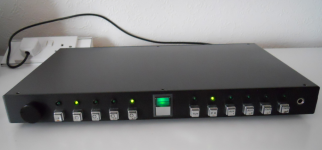
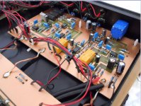
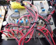
This shows my old preamp and this has three sets of individually controlled buttons. The ones on the right are the input selector, the two sets on the left were for a record in/out switching and a special enhancement circuit. Each button group works individually. This was the set up using the 4017 chips I mentioned. You can see the battery backup on the logic board.
On the diagram with the 4028 chip only the chip is powered by the 5 volt supply and diode and supercap. When you turn the amp off the 5 volt collapses but the cap retains a backup supply for the chip.
The diode stops the backup cap trying to power the rest of the circuit. Does that make sense?
This shows my old preamp and this has three sets of individually controlled buttons. The ones on the right are the input selector, the two sets on the left were for a record in/out switching and a special enhancement circuit. Each button group works individually. This was the set up using the 4017 chips I mentioned. You can see the battery backup on the logic board.
Attachments
Hmm yes I am glad that you always manages to make your explanations fairly simple.
But maybe am I selecting the wrong function to be controlled by buttons?
I am just not sure that a three turn button will look fine, have anyone any thought about that?
Would a two button balance control not be simpler? And then maybe let it start as "center positioned" on power on?
But maybe am I selecting the wrong function to be controlled by buttons?
I am just not sure that a three turn button will look fine, have anyone any thought about that?
Would a two button balance control not be simpler? And then maybe let it start as "center positioned" on power on?
It sounds like you are not sure what you want to control by these buttons/switches. You have to decide how you want to switch the inputs i.e. are you using mechanical switching, relays or electronic switching.
Volume controls can be simple analogue pots that also include remote control (so a motorized pot).
Things balance controls get a whole lot more involved if you want to use 'buttons' to control them. In any case, balance controls once set seldom need adjustment.
Volume controls can be simple analogue pots that also include remote control (so a motorized pot).
Things balance controls get a whole lot more involved if you want to use 'buttons' to control them. In any case, balance controls once set seldom need adjustment.
- Home
- Design & Build
- Construction Tips
- 4 btn Input selector, how?