Does it take both SPDIF (coax) and TTL? If so, won't there be any trouble with 50ohm/75ohm? What IC is this unit based on? (maybe you don't want to give this away).
Yes you can switch any level signal up to VCC. The final termination is not on this board itself (though it could be if you install R1 to taste). By default R1 is a high impedance(=> 47K) which is only used to keep the inputs refernced to GND. You could use any value you like at R1 - or even omit it.
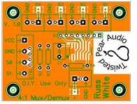
To be more clear - R1 is a 4 resistor array at the "inputs" (they could also be outputs). There is also a single resistor - R4 at the "A" terminal (usually an output). In both cases the default is for those to be high values only used to keep those pins referenced to GND, and they are both optional if termination is provided elsewhere. I used a through hole array at R1 so that users could also use single resistors mounted vertically instead for special cases where different termination is required per channel.
There is no problem sending SPDIF through it, in fact that was how I first tested it (up to 192Khz as that's as high a rate as the source I used went).
For example when using this board with the B3SE the 75R termination occurs at the DAC itself.
It is based on the same technology as the OTTO-II - it is just a 4:1 version of the same chip.
Last edited:
Russ: But when i'm taking about 50/75ohm i'm talking about signal impedance, as same as 75ohm cable. Also, when switching TTL, does the dac terminate with 50ohm (ttl should be 50ohm as far as i can understand).
Also, isn't R4 the termination?
Also, isn't R4 the termination?
I understood you perfectly 🙂
You can terminate externally, at R1 or R4. You can tweak for the characteristic trace impedance if you like, those should be pretty insignificant when used close to the target.
I have been using one direct to a B3SE with R1 at 100K and R4 omitted. Works like a champ.
You can terminate externally, at R1 or R4. You can tweak for the characteristic trace impedance if you like, those should be pretty insignificant when used close to the target.
I have been using one direct to a B3SE with R1 at 100K and R4 omitted. Works like a champ.
Thanks Russ!
But is the Buffalo always terminated with 75ohm at the SPDIF input? (thinking it would be wrong for TTL) Also, what are the R2/R3 for on this PCB? Also when the S0/S1 are "low" can they be floating or do you have to be grounded? "high" i guess is just Vcc. (thinking how i will do with my relay switch).
But is the Buffalo always terminated with 75ohm at the SPDIF input? (thinking it would be wrong for TTL) Also, what are the R2/R3 for on this PCB? Also when the S0/S1 are "low" can they be floating or do you have to be grounded? "high" i guess is just Vcc. (thinking how i will do with my relay switch).
Last edited:
B3SE SPDIF input is terminated at 75R, but if you don't plan on using I2S you could go LVTTL direct to D1 🙂 Just remember not to exceed VCC.
R2 and R3 are optional pull-ups (say 10K). When used your switch should pull to GND. 🙂
R2 and R3 can usually be omitted if you use a controller instead of a switch.
Cheers!
Russ
R2 and R3 are optional pull-ups (say 10K). When used your switch should pull to GND. 🙂
R2 and R3 can usually be omitted if you use a controller instead of a switch.
Cheers!
Russ
Last edited:
Ah i see.. the pull-up resistors are exactly the same function as the one you solder yourself on OTTO-II then 🙂
Dear Brian,
just to order this module together with BIII se I was wondering if we have any expected date...
Thanks in advance,
GM
just to order this module together with BIII se I was wondering if we have any expected date...
Thanks in advance,
GM
gianmaria: This one isn't avaiblie on TP webpage yet.. are you shure it isn't rather the S/PDIF 4:1 MUX/Receiver you ordered?
Dear Brian,
just to order this module together with BIII se I was wondering if we have any expected date...
Thanks in advance,
GM
Boards arrived at my house today. As soon as I get them tested, they will be available.
Dear Brian,
do you foresee any date for the kit to be available? Maybe next week? 🙂
Thank you in advance,
have a great we,
GM
do you foresee any date for the kit to be available? Maybe next week? 🙂
Thank you in advance,
have a great we,
GM
Dear Brian,
do you foresee any date for the kit to be available? Maybe next week? 🙂
Thank you in advance,
have a great we,
GM
Between work and shoulder issues, it's been a pretty unproductive week for me. I have the parts and should be able to get the boards tested/available early next week.
- Status
- Not open for further replies.
- Home
- More Vendors...
- Twisted Pear
- 4:1 or 4:2 mux....