No I am no Sherlock 🙂 who would expect that
Well, You show graphs a bit misleading, as I took it fore granted that the front sim you show, was the one Troels would use - I can see now, one has to be carefull with such things
Apart from that I think I would use it in a even bigger closed box, but then I suppose I am no Einstein either if we are looking at the same driver at all, it appears to me that 75 liter would work both as BR and closed
Ohhh, I see now that Seas specs are very farr from reality ... maybe my name is Sherlock after all 😀 and if Troels measures VAS to be 51.84 instead of 97(which ofcourse is quite much fore a standard 8"), well.... not easy to tell right from wrong in this mess ... apart from 40 liter looking ideal on graphs, and not to expect too heavy lowend
Well, You show graphs a bit misleading, as I took it fore granted that the front sim you show, was the one Troels would use - I can see now, one has to be carefull with such things
Apart from that I think I would use it in a even bigger closed box, but then I suppose I am no Einstein either
if we are looking at the same driver at all, it appears to me that 75 liter would work both as BR and closedOhhh, I see now that Seas specs are very farr from reality ... maybe my name is Sherlock after all 😀 and if Troels measures VAS to be 51.84 instead of 97(which ofcourse is quite much fore a standard 8"), well....
not easy to tell right from wrong in this mess ... apart from 40 liter looking ideal on graphs, and not to expect too heavy lowendPlease Sreten, do you suggest that 50 liter is theoretical ideal when VAS is measured/calculated to be 51.84  well, with VAS=51.8 it does seem to go quite low in 40 liter 🙂
well, with VAS=51.8 it does seem to go quite low in 40 liter 🙂Oh yes, I forgot that Troels also measures Fs to be 38.5 hz instead of factory 29 hz  not the best basis of tuning very low althoug it does appear to have very nice and smooth rolloff
not the best basis of tuning very low althoug it does appear to have very nice and smooth rolloffTinitus....I really got a boot out of your post#593....Thank You for your kind, thoughtful words.............Grant.............The top two air cored inductors are 14 cm apart center to center..............This weekend will bring Frankie closer to his audition, as I will be finishing up the damping materials, and sealing the backs onto the cabinets...........Also, I should be able to get crossovers wired up.....I am gonna go to my sim program to see what resistors values I will be starting with, and I have enough room on the board, should I need to add a shunt cap or two..........I'll keep you posted.............It may take a few days for my cabinet seal to cure before the audition....................Omni...............I probably will have pictures, this weekend, or at the beginning of the week................
 ......
Hi Sreten,
Thanks for your clarification on room gain re: "no ideal general alignment". ( btw, I agree with your 'red-curve '). Also a 20H air-core would probably fill my lounge room, lol....
Hi Omni,
Thanks for your update. Just a suggestion here, FWIW, please see: http://www.troelsgravesen.dk/coils.htm Would it be better to place the top right most (smaller?) coil on its edges and pointing to the top-left coil? You may 'get away with' 14cm spacing 'as is'? I hope you don't mind me mentioning this! thanks guys....grant
Grant, I certainly don't mind your input here, I rather appreciate it.........It probably would insure the elimination of the possibility of inductor interaction if I did place the smaller coil on its edge, as you indicated..............However, depth of crossover space doesn't allow for this............I printed out the article that you referred to and it definately states 20 cm separation would be optimal.........I am thinking that 14 cm is probably not that big of a compromise, in addition to the fact that I put capacitors between the coils. Capacitors are shielded, so part of my thinking is that they may act as a shield between the coils.....Maybe, maybe not .............If there does exist a problem, my possible solution will be to move the left coil further down and away, per the shape of the crossover board.......I should be able to get a 20 cm separation that way................But, then am I bringing that coil too close to the large inductor in the lower left corner of the crossover? I am not sure........The capacitors between the coils on the left are HUGE, which may shield interaction between the coils..........Again, I am not sure..............Another leap of faith.............This is certainly an issue which I have given a lot of thought to............Speaking with a techie about this, he seemed to believe that my layout was OK, but who knows?.........I will keep you posted........................Omni
Omni,
XO ...... if 100% correct one of your air coils should be upright standing
Advise a little late, on the other hand you didnt ask - but anyway Troels has a nice paper on that
Example nr. 6 would be preferred (fig. 5 on shown measurements ?)
That coils actually change value I didnt know
http://www.troelsgravesen.dk/coils.htm
So, when will Frankie play music 🙂
Tinitus.......Thank you for your input....Coil issue all falls on me......A layout with the risk I was willing to take, based on my box dimensions...........If need be, I still have a bit of room for movement of the upper left air coil to attain Troels example #1 example..................So I guess I will take a wait and see approach on this one. I greatly appreciate your concerns............Damping material went in cabinets last nite, and I will be sealing up the backs this evening...........Crossover and driver mounting will occur early part of this week, so I am looking forward to Wednesday, or Thursday for Frankies' 1st audition......I have to exercise patience here, to allow all adhesives to cure fully.......................He's getting closer.............Omni
tinitus said:
....do you suggest that 50 liter is theoretical ideal when VAS is
measured/calculated to be 51.84
does seem to go quite low in 40 liter 🙂
tinitus said:
......not easy to tell right from wrong in this mess ...
Hi,
Quite true. 53L comes up for the standard maximally flat Butterworth.
But as Troels shows you can make it somewhat smaller with a similar
-6dB point but higher -3dB point which suits rooms somewhat better.
I showed the deep bass option that has similar cabinet volume.
🙂/sreten.
Hi Sreten,
I would like to ask you a question please, but ONLY if you have nothing better to do! So, please don't waste any time on it! I saw another alternate design , that you could reject as being irrelevant (?),
however, here goes: The 27TFFC tweeter looks very similar (to me) to the Vifa D27TG-35-06? The graphs are here: http://www.sea.vg/vifa/ Also the P25WO looks close to the M26WR-09-08?
I checked all the drivers frd/zma responses in Roman Bednarek's site in 'SPLView', and they look quite similar to me, ie, T's vs T's, and woofs vs woofs.
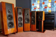
To your probable dismay, I've been looking at another open baffled M/T design here:
http://www.pinkfishmedia.net/forum/showthread.php?t=8135
James, the designer, initially used the D75MX Vifa mid but then changed to the Seas MCA15RCY, and still using the Vifa tweeter. He has quite a few nice looking designs on that site, attached, but not the 'PFM-Special'.
I guess I'm wondering if the 'PFM-Special' could be modified for my P25's and proposed 27TFFC's? This is a huge ask of you, I know....and *only* please if you have nothing better to do! A pic of the other James 'Ergo' creations is attached...they look stunning to me! James says on the last page that a 'mod' would be difficult, and expensive, but I'm still wondering.....because the tweeters look so similar,
and the P25 vented 40Litre might just do? ...if you reply to this, I'll be very grateful!...grant
I would like to ask you a question please, but ONLY if you have nothing better to do! So, please don't waste any time on it! I saw another alternate design , that you could reject as being irrelevant (?),
however, here goes: The 27TFFC tweeter looks very similar (to me) to the Vifa D27TG-35-06? The graphs are here: http://www.sea.vg/vifa/ Also the P25WO looks close to the M26WR-09-08?
I checked all the drivers frd/zma responses in Roman Bednarek's site in 'SPLView', and they look quite similar to me, ie, T's vs T's, and woofs vs woofs.
To your probable dismay, I've been looking at another open baffled M/T design here:
http://www.pinkfishmedia.net/forum/showthread.php?t=8135
James, the designer, initially used the D75MX Vifa mid but then changed to the Seas MCA15RCY, and still using the Vifa tweeter. He has quite a few nice looking designs on that site, attached, but not the 'PFM-Special'.
I guess I'm wondering if the 'PFM-Special' could be modified for my P25's and proposed 27TFFC's? This is a huge ask of you, I know....and *only* please if you have nothing better to do! A pic of the other James 'Ergo' creations is attached...they look stunning to me! James says on the last page that a 'mod' would be difficult, and expensive, but I'm still wondering.....because the tweeters look so similar,
and the P25 vented 40Litre might just do? ...if you reply to this, I'll be very grateful!...grant
Attachments
hi,
anywhere there are straightforward details of the PFM-special ?
What is Fs, Qts and Vas of your woofer ?
🙂/sreten.
anywhere there are straightforward details of the PFM-special ?
What is Fs, Qts and Vas of your woofer ?
🙂/sreten.
Wow, Thanks Sreten!
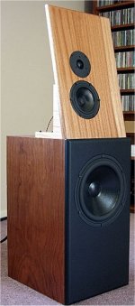
The 'PFM-Special' pic is attached. I remember that you said Tony Gee's open baffle design was a bit esoteric? or words to that effect, I think, so I'm not sure yet of your thoughts on this one. Imho,
the top baffle would look better black! The designer , James, says it sounds really good with D27TG-35-06, the MCA15RCY and M26WR-09-08's. From what I can see the Seas 27TFFC looks like a drop-in replacement of the D27TG, only better perhaps? I just noticed a post in the 'PFM' thread that says these Vifa and Seas tweeters have similar responses, but don't sound anything alike! Troels, however matches the Seas T and M in his PMS, seemingly quite successfully, so who knows!
The designer says the M26WR was borderline for his closed box, so he changed its Qts by a series resistor , I think. My P25, if, its possible to use in this design, would still be vented.
The M26 has Fs = 26Hz, Vas = 130 Litres, Re = 5.9 ohms , Le = 1.8 mH ,Qts = 0.32, Sd = 337 cm^2.
The P25 has Fs = 24Hz, Vas = 178 Litres, Re = 5.7 Ohms , Le = 2.2mH , Qts = 0.28, Sd = 346 cm^2.
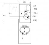
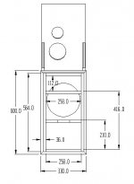
They look kinda close to me, but I really don't know, of course. The M26 is (from memory) in a 40 litre closed box, and the MCA15 is open. I'll post the basic enclosure detail and xo, soon.
I just thought this might be a viable alternative to me if the Seas tweeter and P25 compromise could be used. My idea is to match the 27TFFC with the MCA15 in this case, if possible, as an initial least cost option, and if it didn't work out, then I would have 2(of 3) drivers to build an exact PMS. I'd buy the CA22RNX's later. But therein lies a problem...the PMS plans don't seem finalised and I think you mentioned the bracing needs work. Hmm, I'll try to fix that later somehow when I build the PMS enclosures, if necessary.
Many thanks Sreten, I really do appreciate your learn-ed advice! ....grant
(if anyone else is reading this and wants the 'PFM-Special' details, it starts here...
http://www.pinkfishmedia.net/forum/showthread.php?t=8135&page=1 ...currently 15 pages )
The 'PFM-Special' pic is attached. I remember that you said Tony Gee's open baffle design was a bit esoteric? or words to that effect, I think, so I'm not sure yet of your thoughts on this one. Imho,
the top baffle would look better black! The designer , James, says it sounds really good with D27TG-35-06, the MCA15RCY and M26WR-09-08's. From what I can see the Seas 27TFFC looks like a drop-in replacement of the D27TG, only better perhaps? I just noticed a post in the 'PFM' thread that says these Vifa and Seas tweeters have similar responses, but don't sound anything alike! Troels, however matches the Seas T and M in his PMS, seemingly quite successfully, so who knows!
The designer says the M26WR was borderline for his closed box, so he changed its Qts by a series resistor , I think. My P25, if, its possible to use in this design, would still be vented.
The M26 has Fs = 26Hz, Vas = 130 Litres, Re = 5.9 ohms , Le = 1.8 mH ,Qts = 0.32, Sd = 337 cm^2.
The P25 has Fs = 24Hz, Vas = 178 Litres, Re = 5.7 Ohms , Le = 2.2mH , Qts = 0.28, Sd = 346 cm^2.
They look kinda close to me, but I really don't know, of course. The M26 is (from memory) in a 40 litre closed box, and the MCA15 is open. I'll post the basic enclosure detail and xo, soon.
I just thought this might be a viable alternative to me if the Seas tweeter and P25 compromise could be used. My idea is to match the 27TFFC with the MCA15 in this case, if possible, as an initial least cost option, and if it didn't work out, then I would have 2(of 3) drivers to build an exact PMS. I'd buy the CA22RNX's later. But therein lies a problem...the PMS plans don't seem finalised and I think you mentioned the bracing needs work. Hmm, I'll try to fix that later somehow when I build the PMS enclosures, if necessary.
Many thanks Sreten, I really do appreciate your learn-ed advice! ....grant
(if anyone else is reading this and wants the 'PFM-Special' details, it starts here...
http://www.pinkfishmedia.net/forum/showthread.php?t=8135&page=1 ...currently 15 pages )
Attachments

- Status
- Not open for further replies.
- Home
- Loudspeakers
- Multi-Way
- 3way XO help greatly appreciated!