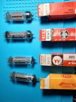
As noted in the SPP threads, out of a small sample number of 6CW5 tubes i found here at the office, I also have the two distinct sub types.
The small tube is an RCA made in Canada. It has no grid fins.
The second tube was in an RCA box, but it doesn't look like an RCA tube. Look at the size of the grid fins on the tube.
The Motorola branded tube is marked made in W. Germany without any other manufacturer information that I can tell. Being Motorola, It was likely sourced from a premium manufacturer.
The last tube is a late production Ei. It is very similar to, but not identical to the Motorola tube.
Attachments
Hello,
What material you use for printing?
I've used printed cases for several years now, mainly PETG, never PLA. Shielding is not an issue, I use this: https://www.ret.hu/shop/product/kontakt-chemie/emv-emi-35-200ml_80-00-30 and it works fine. A solid contact point may not be easy to make, but what I do is I use one of the screw of the IEC socket and a toothed washer.
On the other hand, I've never used 3D print for tube circuit housing. I've tried, ordered PC-FR for that. Prints nice on small objects, but shrinks so much that I could not print a larger object, no matter what chamber temperature I've set on my P1S Bambu. I can print ASA or ABS object, but PC-FR is a challenge to me.
Now from your post I'm thinking in a hybrid solution. How about using a metal plate and print only a frame? I think for the frame, PC or PC-FR should work.
Regards,
JG
This one is made from ordinary inexpensive PLA, and I think I used 30% infill. I do have some "high heat" PLA but at this low power level, I am already confident that heat is not a problem.
How well, if at all, this will scale up for heavier, hotter, amps is still unknown.
The hybrid approach of a metal plate on a printed frame might be a good technique. That would still be a big time saver compared to the usual construction techniques.
Win W5JAG
How well, if at all, this will scale up for heavier, hotter, amps is still unknown.
The hybrid approach of a metal plate on a printed frame might be a good technique. That would still be a big time saver compared to the usual construction techniques.
Win W5JAG
I would strongly suggest to stay away from PLA. I have things printed about 10 years ago what is literally falling apart. Was printed correctly, but PLA dies fast and without UV.
PETG is very easy to print also and you do not need enclosed printer still. On the other hand, you can count on it long term and heat resistance is better too.
I'm not sure it is interesting in your application, but I play with some parts where resonance plays important role and I do annealing after printing on those. On things like turntable stand it does make a difference. With annealing you take out the stress from the printed part. It is easy to do, even with a better kitchen oven. You print a few similar parts and find the maximum temperature where the printed part does not deform at all yet. You set that temperature for 10min and it works fine. It actually improves mechanical characteristics too, it breaks less, especially between layers. You take the same part before and after annealing, kick it with something and it sounds different. After annealing it sounds more "dead". It sound lower in frequency and "ringing" for much shorter period of time.
TPU is also excellent for feets for example, if you have direct extruder.
JG
I have some petg, but haven't used it yet.
The high heat pla that I have is supposed to go through a heat process in the oven after it is printed, similar to your annealing process, but I haven't used it so I am not certain of the exact process.
10 year lifespan is totally OK with me.
Win W5JAG.
The high heat pla that I have is supposed to go through a heat process in the oven after it is printed, similar to your annealing process, but I haven't used it so I am not certain of the exact process.
10 year lifespan is totally OK with me.
Win W5JAG.
Here are some results of various combinations of 6X5 and 6AX5 rectifier tubes, 6CW5 and 6BQ5 power tubes, and 6C4 and 6AB4 driver tubes.
To cut to the chase, the results are:
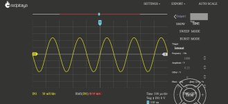
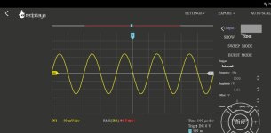
6AX5/6CW5/6AB4: 0.23 VRMS input to clip; 29 dBm output; 3% THD
6AX5/6CW5/6C4: 0.65 VRMS input to clip; 29 dBm output; 2.5% THD
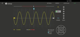
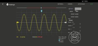
6X5/6BQ5/6AB4: 0.12 VRMS input to clip; 31 dBm output; 2% THD
6X5/6BQ5/6C4: 0.36 VRMS input to clip; 31.5 dBm output; 2.2% THD
To cut to the chase, the results are:
6AX5/6CW5/6AB4: 0.23 VRMS input to clip; 29 dBm output; 3% THD
6AX5/6CW5/6C4: 0.65 VRMS input to clip; 29 dBm output; 2.5% THD
6X5/6BQ5/6AB4: 0.12 VRMS input to clip; 31 dBm output; 2% THD
6X5/6BQ5/6C4: 0.36 VRMS input to clip; 31.5 dBm output; 2.2% THD
As expected, the 6AB4 takes about one third the drive of the 6C4 to achieve clipping. I suspect the lower output of the 6CW5 is down to the very wrong load resistance, and the 6BQ5 to not enough voltage / current.
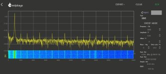
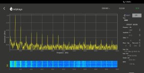
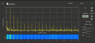
Although the overall THD of the combinations is pretty similar, the FFT spectrums of the tubes are different. The THD number should be viewed with caution, since it has to be calculated from the FFT, and the absolute value of the harmonics has to be eyeballed. My Red Pitaya only calculates an exact value for the strongest signal in the spectrum bandwidth.
There are two different types of 6X5 rectifiers; the tube used here is the more modern crossed X style. Similarly, there is more than one construction type of 6AX5 rectifier. The tube used here is the GE variant that uses the guts from the 6087 (5Y3WGTB) rectifier tube. I mention this not to sound like an audiophile, but because even with my mediocre test equipment, I have measured differences in distortion with different construction rectifier tubes, even though they have insignificant differences in voltage output.
The 6CW5 is the small plate, made in Canada version. Under load, the 6AX5 rectifier delivers 166 volts to the 6CW5 plate, and the cathode voltage is 12.8. With a 200 ohm cathode resistor, that is 64 milliamps current drawn; about 10 watts plate dissipation. This is essentially the data sheet values for one tube in class A. The cathode bypass resistor is 100 uF.
The 6BQ5 and 6CW5 are triode wired. The grid resistor is 240K - this may be a little low but seems to be okay. The CCS was adjusted for 1.25 volts bias for both 6C4 and 6AB4. There is no external feedback.
All of the measurements are with the 7K tap on the output transformer. This is a reasonable value for the 6BQ5, and too high for the 6CW5, which should have 2-3K. I tried using the 5K tap on the OPT, but after hours of tinkering, eventually came to the realization that it is just unusable. I don’t know why that is so, but no matter what I did, I could not get more than about 50 milliwatts output from the 5K tap. The 7K tap works okay, not great, but not terrible, either.
I used a 14-bit Red Pitaya (RP) with its internal signal generator to make the measurements. I made a 30 dB, 8 ohm T attenuator for the amplifier load, placed in series between the amp output and the Red Pitaya input. I made a baseline loop back of the Red Pitaya at the 0.65 VRMS output (the maximum required to drive the amp to clipping) and calculated its THD to be 0.05% at that level, so basically insignificant. The clipping point I use is conservative - any observable deviation, no matter how slight, from a pristine sine wave I consider the clip point. The RP has two outputs, so I should be able to use it to see IMD, but I’m not sure of the best way to combine the two outputs. I brought my Hantek scope up, and played with using it a bit, but I decided the RP was just more convenient.
Right now, I am using the 6AX5/6CW5/6C4 combination for a couple of reasons: with the small speaker I am using, I thought this combination sounded best. It also runs much hotter than the 6X5/6BQ5 combination, so helps to better assess a major objective - to see if the printed chassis is useful. After a few hours, the transformer gets too hot to comfortably touch. The chassis remains cool since the transformer is slightly elevated above it. The chassis around the tube sockets is also cool.
The bottom plate has ventilation holes molded in for air circulation. I believe in the thread in the main tube forum about cooling, there was no real agreement on whether or not this was necessary or even useful. My hand tells me that the heat builds up much faster in the transformer when the bottomless amp is placed on the table, preventing air circulation up through and around it. It is literally zero effort to add ventilation since the 3D printer makes all the holes or slots, so I see no harm in doing it. I use stick on rubber feet on the bottom plate to raise it a few mm for air circulation.
Attachments
-
 RP_065v_loopback.jpg81.4 KB · Views: 69
 -
 6X5_6AB4_6BQ5_1.25v_FFT.jpg91.7 KB · Views: 63
 -
 6X5_6C4_6BQ5_1.25v_FFT.jpg90.8 KB · Views: 66
 -
 6AX5_6AB4_6CW5_1.25v_FFT.jpg80 KB · Views: 62
 -
 6AX5_6C4_6CW5_1.25v_FFT.jpg77.4 KB · Views: 59
 -
 6AX5_6AB4_6CW5_1.25v_scope.jpg49.3 KB · Views: 62
 -
 6AX5_6C4_6CW5_1.25v_scope.jpg49.8 KB · Views: 60
 -
 6X5_6AB4_6BQ5_1.25v_scope.jpg54.2 KB · Views: 54
 -
 6X5_6C4_6BQ5_1.25v_scope.jpg57.6 KB · Views: 55
Plastic case means no screening and no earthing of case. Not my preference for a tube amp…
After having it in service for a couple of months, neither of these concerns are an issue in my particular application. The service location of this amp is an RF environment, albeit pretty low power, generally less than 10 watts. It is within a couple of feet of my transmitter, and about eight feet of the antenna feedpoint. The HF antenna is coax fed, but just a simple end fed wire with a 49:1 balun at the feed. This type is among the most likely to cause problems with RFI in other devices. The VHF antenna is a simple half wave dipole. No problems with RFI have been apparent.
The FFT's look to show a hum component about -60 dB. I think this is more likely an artifact of the power supply design, or the measurement setup, than the plastic chassis but can't say for certain. It is not a problem with the 4-inch speaker in its intended application; it could be a problem with the 97 dB sensitive Klipsch speakers downstair, but I haven't tried it on the hi fi speakers.
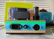
The transformer, 6AX5, and 6CW5 get really hot. The transformer runs much hotter than I would ordinarily expect; I don't cate to touch the top plate for more than a few seconds after it has been on for a couple of hours. I have ran it as long as 24 hours continuously, and frequently 8-10 hours continuously when I am up here at this house, and the chassis has always felt cool to me.
The only consequence of this that is apparent is that the right rear corner looks to have dropped about 1/16th of an inch. I never noticed this until this morning. It could have been there a while, or slowly accruing over time. I don't normally look at the amp from the rear, and it's not apparent from a head on view. The picture attached shows the drop. The perspective makes it look worse than it really is. I'll keep an eye on it over time. It could be cured with a slightly taller spacer if it gets cosmetically annoying. I don't think it is any kind of a structural problem.
Attachments
- Home
- More Vendors...
- Tubelab
- 3D printed SSE parts and another DH SSE part 2