hello all..
before i went ahead with building the boost converter i just wanted to confirm that i am on the right path and that my calculations are correct so far.
Heres the idea
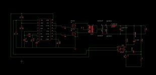
i wanted to build a 36v to 400 v boost converter capable of delivering 100w
the supply voltage is 36 v
here is the schematic i arrived at.
The transformer has primary turns of 6 (swg 21) and secondary turns of 84 (swg 35)
It is a EE28 transformer
i wanted some light on whether the method of isolated feedback i used here is correct or not and whether the values of the components i arrived at for the specfic case are correct.
i have not yet given the values of the gate resistors as i first wanted to confirm that my PWM modulator ckt is acceptable.
attached are the eagle files and the bmp of the same
any help is highly appreciated
before i went ahead with building the boost converter i just wanted to confirm that i am on the right path and that my calculations are correct so far.
Heres the idea
i wanted to build a 36v to 400 v boost converter capable of delivering 100w
the supply voltage is 36 v
here is the schematic i arrived at.
The transformer has primary turns of 6 (swg 21) and secondary turns of 84 (swg 35)
It is a EE28 transformer
i wanted some light on whether the method of isolated feedback i used here is correct or not and whether the values of the components i arrived at for the specfic case are correct.
i have not yet given the values of the gate resistors as i first wanted to confirm that my PWM modulator ckt is acceptable.
attached are the eagle files and the bmp of the same
any help is highly appreciated
Attachments
sorry
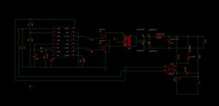
forgot to mention in the schematic
the cathode of the TL431 is connected to the return of the output
and here is the updated schematic
forgot to mention in the schematic
the cathode of the TL431 is connected to the return of the output
and here is the updated schematic
Attachments
Last edited:
no comment on the values and calculations??
🙁
i didnt know that a TL431 compensated feedback is such a well kept secret in the SMPS community...
😀
🙁
i didnt know that a TL431 compensated feedback is such a well kept secret in the SMPS community...
😀
A few comments:
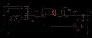
1. I don't see a snubber to disapate voltage spikes caused by inductance leakage. You need a Snubber to avoid exceeding your MOSFET voltage limit.
2. No flux walking compensation. Unless your manage to wind both legs of your primary push-pull exactly equal, you likely have flux walking problem that will cause transformer core saturation. You need to add some Dead time between switching cycles (ie a resistor between CT and Discharge)
3. Something does look right with your TL431 connection. You don't appear to have an connection to the output ground. Both connections are connected to the output supply connection.
finally...
😀
@techguy
thank you..
1)i havent drawn the sunbber as i have not yet started working on that part.
i first wanted to get my circuit level diagram right.
the gate resistors and the snubbers will be there after i trial run the set up once to measure the parameters.
2)i havent drawn the flux walking capacitor as i drew the ckt in a haste
i have about 1 us deadtime for a 10 us ts.
3) in my second post i did correct that mistake and connect the cathode of the TL431 to the output return.
thanks for your suggestions.
🙂
now i can trial test it...
- Status
- Not open for further replies.
- Home
- Amplifiers
- Power Supplies
- 36v to 400v boost converter