Can you buy a 360 degree phase switch for a subwoofer or do you have to make them ? How would you make such a switch ?
Since 360 degrees is equivalent to 0 degrees, I'm not sure what you want. Did you mean a 180 degrees switch?
Rune
Rune
Sorry, perhaps I used the wrong terminology. Basically I want a variable phase switch, a sweep from, in phase to out of phase, is this 180 ?
Hi Puffin, the easy way out is to purchase a plate amplifier for your subwoofer. Some of them got a switch between 0 and 180 degrees and others got a knob for continously variable phase between 0 and 180 degrees.
I'd also be interested in DIY-ing such a continuously variable phase adjustment. Buyout plate amps aren't really my "thing" (i was thinking of a BPA300 with 6xLM3886), so a separate schematic or circuit diagram would be real nice 
Varying from 0 to 180 then swapping the cable polarity and again varying from 0 to 180 - gives all the possibilities.
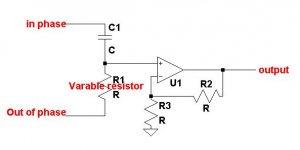
In order to have vairable phase you need to have an in phase signal and the same signal 180 degrees out of phase. You then use a potentiometer and a capacitor as a potential divider between the signals. The output from the pot div will vairy between 0 and 180 degrees depending on the variable resistor.
This can be done using transistors or opamps, Transistors are probaly easier as you would only need the one.
This can be done using transistors or opamps, Transistors are probaly easier as you would only need the one.
bob123 , that sounds intriguing... Considering that my sub amp is going to be a BPA300-type thing (as per www.shine7.com/audio/bpa300.htm ), i will have both the in-phase signal AND the 180 reverse phase signal.
Do you have a schematic of some sort, or some link(s)?
Do you have a schematic of some sort, or some link(s)?
Whew.. that's gonna make the "preamp" board a wee bit more crowded 🙂 I'm gonna have to fit TWO SE->balanced converters (one to get the signals for the phase controller, and the second one after it, to drive the two amps). Guess i have a bit of "homework" to do... 😀
Bob123. Thanks for the simple schematic. The problem is I am very simple ! I don't suppose you are able to give values for the components, op-amp, resisitors etc.
runebivrin said:
This will give you all the values, and some additional tips.
Rune
That looks much more complicated than Bob123's simpler suggestion. I suppose I could just use part of it using the values suggested ?
It's not done that way. It's done using a (multi-stage) phase shifter (also called Allpass Filter) like the rightmost op-amp shown in the schematic from Rod Elliot's page.
See also the resulting phase plots from that page. A constant delay is introduced in the signal up to the frequency where the pase is 90 degrees, then the delay progressively falls to 0 for higher frequencies as phase approaches 180 degrees. The amplitude of the signal remains unchanged for all frequencies.
The best control is achieved by allowing independent adjustment of each phase shifter stage (sometimes up to four are required to get decent phase match between very dissimilar drivers or horns in the crossover region).
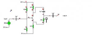
Here is a constant amplitude phase splitter, uses transistors so biasing values e.t.c are critical.
Im not sure how stable this is at temperature but it is an emitter degeneration amplifer so has negative feedback.
The phase shift is not constant for all frequencys but i doubt that will matter for a very small frequency range such as a subwoofer bandwidth.
All values are critical on this design! Dont change them or it wont work. (except for RC)
keep impedance high on the next stage as well. Probaly bout 200kohm.
- Status
- Not open for further replies.
- Home
- Loudspeakers
- Subwoofers
- 360 degree phase switch