Hi All the friends,
I am new in this forum......
I want built 300w mosfet amplifier for my car, So I got this schematic(attached) for this project so give me advice how is SMPS and if any problems in AMP's schematic at any where.
Thanking you all
with best regards
I am new in this forum......
I want built 300w mosfet amplifier for my car, So I got this schematic(attached) for this project so give me advice how is SMPS and if any problems in AMP's schematic at any where.
Thanking you all
with best regards
Attachments
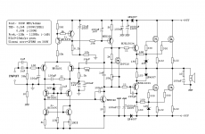
The amp looks ok at a glance. But my question is how your going to power this with 95 volt rails ???
That's a 190 volt supply needed from a car's 12 volt supply. I guess you could rectify and filter a 12 volt to 120 inverters output to maybe get sufficient rails voltage to power this amp. Plus I would be adding fuses for some protection from fire if the amp fails..
Why not just buy one of the many available pre-designed units on the market? it would save you a bunch of work and time.....🙂
1moreamp said:The amp looks ok at a glance. But my question is how your going to power this with 95 volt rails ???
That's a 190 volt supply needed from a car's 12 volt supply. I guess you could rectify and filter a 12 volt to 120 inverters output to maybe get sufficient rails voltage to power this amp. Plus I would be adding fuses for some protection from fire if the amp fails..
Why not just buy one of the many available pre-designed units on the market? it would save you a bunch of work and time.....🙂
Hi Friend,
Thanks for reply, But I want buiit my own amlifier for my car because i am basicaly electronics technician.I'll give the 50V to 60V supply to this amplifier.
Can i use any transistor at IRF510 ?
Thanks
With Regards
The IRF510 MOSFET is used as a thermal bias sensor so I would be inclined to think a generic MOSFET might work. But this should be tested for stability and proper operation. I have a bunch of these laying around they are pretty common here in the states.
And changing the rail supply will cause all sorts of design concerns to crop up as I am sure there several places where the resistor values are set for the higher rail supply.
If I were headed into your project I would try to get some Simulation software and see what happens with the lower rails before risking any set backs in the real world.
As most designs are voltage relevant and at the lower supply your talking about there will be a fairly huge drop off in the output power rating unless your running lower ohm loads.
60 volt rails in car amps are not that common, unless its a class D design. Then high voltage is the norm in most cases. Amps like the PG MS-2250 have rails in the 63 volt range and these amps are famous for getting super hot and shutting down from heat related issues. Class AB designs are just not energy efficient, and the heat build up has always been a issue in car audio for high voltage amps. PG had cooling shrouds custom built for there monster maps with 63 volt rails inside them. Others just used over-sized heatsinks to combat the issue.
35 to 45 volt rails are fairly common especially in MOSFET designs. There are a few other places here on this forum like "Solid State" Where folks Sim amps for each other while doing redesign work on them. I would check those areas out also as there is always a bunch of design efforts going on over there....🙂
- Status
- Not open for further replies.