I'm preety new to the whole thing and I know that the transformers must be at the 90 degree angle to one another but like haven't found any tips on caps and such, heater supply also, do you have any advice on how I should I do that? Point to point construction of course.
300B SE Amp
Hum reduction:
Use an aluminum chassis.
Magnetic steel conducts magnetic fields from the power transformer and B+ choke to the output transformer.
If you must use a magnetic steel chassis, elevate the SE output transformer off of the chassis with spacers to reduce the magnetic fields to the output transformer. A 1/4 inch of space should make some improvement of hum levels.
Some kinds of stainless steel are not magnetic, or only mildly magnetic.
Put the power transformer(s) and B+ choke at one end of the chassis, and put the output transformer at the other end of the chassis.
Orient the power transformer coil and B+ choke coil in one direction. Then orient the output transformer coil at right angles to that of both the power transformer and choke coils.
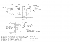
Your schematic does not show a filament winding for the 300B. Do Not use the same 5V filament winding that the rectifier tube filament uses. That will burn out a lot of parts and circuits.
You could use the 6.3V winding, and two series resistors, 0.5 Ohm 3 or 5 Watt each.
Wire from one end of the 6.3V winding to one end of the 0.5 Ohm, and the other end of the 0.5 Ohm to pin 1 of 300B. Wire from pin4 of 300B to one end of the other 0.5 Ohm, then the other end of that 0.5 Ohm to the other end of the 6.3V winding.
That series circuit is: start of 6.3V, 0.5 Ohm, 300B, 0.5 Ohm, return of 6.3V.
Or, you are going to need another transformer to power the 300B 5V filament.
The hum pot on the filament will allow you to null out some of the hum. That gets you up and running.
But you probably will eventually want to use a floating 5VDC supply for the 300B filament. That will reduce the Intermodulation of 2 x the line frequency on the test sine waves, and on the music notes. 50Hz power x 2 = 100 Hz intermodulation; 60Hz power x 2 = 120Hz.
You could start with a floating 5VDC supply, but that does complicate your fairly simple and straightforward schematic (does not change anything on your schematic, but adds the circuitry of a filament transformer, solid state rectifier, filter caps, resistor, and another filter cap (CRC).
Now, lets prevent a major cause of hum: The B+ ground loop.
Connect the B+ high voltage secondary Center Tap directly to the negative lead of C6.
Connect a wire from negative lead of C6 to both negative leads of C7.
The point is that you do not directly connect the center tap nor the negative lead of C6 to the central ground point of the amplifier. But after you connect the negative of C6 to negatives of C7, only then do you connect the negatives of C7 to a central ground point.
The central ground point is where Most the grounds and returns connect.
You also connect this central ground point to the chassis. That shields the other circuitry.
Connect the following to a central ground point:
The negative leads of C7; bottom of R3 C2; R6 C4; the negative lead of C5; the Chassis; the Common of the output transformer secondary; and the bottom of R1 C1.
Use insulating shoulder washers to isolate the RCA phono input jack from the chassis. Then connect the outside of that RCA jack to the bottom of R1 C1.
The reduces the input ground loop.
Safety:
We have accounted for all the grounds, except possibly one:
In the US we have 3 wire power, Hot, Neutral, and Ground.
I use a 3-wire IEC socket on the amplifier, and a 3-wire plug to IEC cord.
On my power amplifiers, I connect the Ground of that IEC input socket to the chassis.
That provides safety for those who might come in contact the chassis. (even if there is a short of B+, or output transformer primary to the chassis, there is no shock danger.
Safety First!
Your power mains may or may not require that, I do not know what your power mains are like in your country.
All my other audio equipment: CD player, Phono Preamp, Turntable, and AM FM Tuner have 2 wire power cords. But those are UL and CSA safety rated to be used with 2 wire power cords. They do not have an exposed chassis that I could touch, and the only other points on them are the RCA phono jacks, and they end up connecting to each other which means they are ultimately connected to the power amp, and the power amp inputs are grounded to the input bias circuit, and from there to the central ground point of the amp, and to the 3-wire power mains ground.
Use a chassis that allows the tubes to breathe, and so you can space your tubes away from any heat sensitive parts, like an electrolytic that is on the top of the chassis.
Safety First!
I use both a fast blow fuse, and a slow blow fuse in series. That protects my amp from different kinds of failures.
For example, I have an amp that uses a 1.25 Amp fast blow, in series with a 600mA slow blow.
That amp has solid state diodes in the B+ supply. And filaments are very low resistance when cold; both of those creates an inrush transient current at turn on, the 1.25A protects against that. The slow blow is not affected by the transient, but if one of the tubes starts to fail and draws too much current, or if an electrolytic begins to fail, the 600mA slow blow will open.
Safety First!
Shhh, don't tell anyone, but I am building a 300B SE amp again, but this time I will use 5VDC not AC for the 300B filament.
And I plan on building a 2A3 SE amp again, but this time I will use 2.5VDC not AC for the 2A3 filament.
Happy building, and happy listening.
Hum reduction:
Use an aluminum chassis.
Magnetic steel conducts magnetic fields from the power transformer and B+ choke to the output transformer.
If you must use a magnetic steel chassis, elevate the SE output transformer off of the chassis with spacers to reduce the magnetic fields to the output transformer. A 1/4 inch of space should make some improvement of hum levels.
Some kinds of stainless steel are not magnetic, or only mildly magnetic.
Put the power transformer(s) and B+ choke at one end of the chassis, and put the output transformer at the other end of the chassis.
Orient the power transformer coil and B+ choke coil in one direction. Then orient the output transformer coil at right angles to that of both the power transformer and choke coils.
Your schematic does not show a filament winding for the 300B. Do Not use the same 5V filament winding that the rectifier tube filament uses. That will burn out a lot of parts and circuits.
You could use the 6.3V winding, and two series resistors, 0.5 Ohm 3 or 5 Watt each.
Wire from one end of the 6.3V winding to one end of the 0.5 Ohm, and the other end of the 0.5 Ohm to pin 1 of 300B. Wire from pin4 of 300B to one end of the other 0.5 Ohm, then the other end of that 0.5 Ohm to the other end of the 6.3V winding.
That series circuit is: start of 6.3V, 0.5 Ohm, 300B, 0.5 Ohm, return of 6.3V.
Or, you are going to need another transformer to power the 300B 5V filament.
The hum pot on the filament will allow you to null out some of the hum. That gets you up and running.
But you probably will eventually want to use a floating 5VDC supply for the 300B filament. That will reduce the Intermodulation of 2 x the line frequency on the test sine waves, and on the music notes. 50Hz power x 2 = 100 Hz intermodulation; 60Hz power x 2 = 120Hz.
You could start with a floating 5VDC supply, but that does complicate your fairly simple and straightforward schematic (does not change anything on your schematic, but adds the circuitry of a filament transformer, solid state rectifier, filter caps, resistor, and another filter cap (CRC).
Now, lets prevent a major cause of hum: The B+ ground loop.
Connect the B+ high voltage secondary Center Tap directly to the negative lead of C6.
Connect a wire from negative lead of C6 to both negative leads of C7.
The point is that you do not directly connect the center tap nor the negative lead of C6 to the central ground point of the amplifier. But after you connect the negative of C6 to negatives of C7, only then do you connect the negatives of C7 to a central ground point.
The central ground point is where Most the grounds and returns connect.
You also connect this central ground point to the chassis. That shields the other circuitry.
Connect the following to a central ground point:
The negative leads of C7; bottom of R3 C2; R6 C4; the negative lead of C5; the Chassis; the Common of the output transformer secondary; and the bottom of R1 C1.
Use insulating shoulder washers to isolate the RCA phono input jack from the chassis. Then connect the outside of that RCA jack to the bottom of R1 C1.
The reduces the input ground loop.
Safety:
We have accounted for all the grounds, except possibly one:
In the US we have 3 wire power, Hot, Neutral, and Ground.
I use a 3-wire IEC socket on the amplifier, and a 3-wire plug to IEC cord.
On my power amplifiers, I connect the Ground of that IEC input socket to the chassis.
That provides safety for those who might come in contact the chassis. (even if there is a short of B+, or output transformer primary to the chassis, there is no shock danger.
Safety First!
Your power mains may or may not require that, I do not know what your power mains are like in your country.
All my other audio equipment: CD player, Phono Preamp, Turntable, and AM FM Tuner have 2 wire power cords. But those are UL and CSA safety rated to be used with 2 wire power cords. They do not have an exposed chassis that I could touch, and the only other points on them are the RCA phono jacks, and they end up connecting to each other which means they are ultimately connected to the power amp, and the power amp inputs are grounded to the input bias circuit, and from there to the central ground point of the amp, and to the 3-wire power mains ground.
Use a chassis that allows the tubes to breathe, and so you can space your tubes away from any heat sensitive parts, like an electrolytic that is on the top of the chassis.
Safety First!
I use both a fast blow fuse, and a slow blow fuse in series. That protects my amp from different kinds of failures.
For example, I have an amp that uses a 1.25 Amp fast blow, in series with a 600mA slow blow.
That amp has solid state diodes in the B+ supply. And filaments are very low resistance when cold; both of those creates an inrush transient current at turn on, the 1.25A protects against that. The slow blow is not affected by the transient, but if one of the tubes starts to fail and draws too much current, or if an electrolytic begins to fail, the 600mA slow blow will open.
Safety First!
Shhh, don't tell anyone, but I am building a 300B SE amp again, but this time I will use 5VDC not AC for the 300B filament.
And I plan on building a 2A3 SE amp again, but this time I will use 2.5VDC not AC for the 2A3 filament.
Happy building, and happy listening.
Last edited:
300B SE Amp
Hum reduction:
Use an aluminum chassis.
Magnetic steel conducts magnetic fields from the power transformer and B+ choke to the output transformer.
If you must use a magnetic steel chassis, elevate the SE output transformer off of the chassis with spacers to reduce the magnetic fields to the output transformer. A 1/4 inch of space should make some improvement of hum levels.
Some kinds of stainless steel are not magnetic, or only mildly magnetic.
Put the power transformer(s) and B+ choke at one end of the chassis, and put the output transformer at the other end of the chassis.
Orient the power transformer coil and B+ choke coil in one direction. Then orient the output transformer coil at right angles to that of both the power transformer and choke coils.
Your schematic does not show a filament winding for the 300B. Do Not use the same 5V filament winding that the rectifier tube filament uses. That will burn out a lot of parts and circuits.
You could use the 6.3V winding, and two series resistors, 0.5 Ohm 3 or 5 Watt each.
Wire from one end of the 6.3V winding to one end of the 0.5 Ohm, and the other end of the 0.5 Ohm to pin 1 of 300B. Wire from pin4 of 300B to one end of the other 0.5 Ohm, then the other end of that 0.5 Ohm to the other end of the 6.3V winding.
That series circuit is: start of 6.3V, 0.5 Ohm, 300B, 0.5 Ohm, return of 6.3V.
Or, you are going to need another transformer to power the 300B 5V filament.
The hum pot on the filament will allow you to null out some of the hum. That gets you up and running.
But you probably will eventually want to use a floating 5VDC supply for the 300B filament. That will reduce the Intermodulation of 2 x the line frequency on the test sine waves, and on the music notes. 50Hz power x 2 = 100 Hz intermodulation; 60Hz power x 2 = 120Hz.
You could start with a floating 5VDC supply, but that does complicate your fairly simple and straightforward schematic (does not change anything on your schematic, but adds the circuitry of a filament transformer, solid state rectifier, filter caps, resistor, and another filter cap (CRC).
Now, lets prevent a major cause of hum: The B+ ground loop.
Connect the B+ high voltage secondary Center Tap directly to the negative lead of C6.
Connect a wire from negative lead of C6 to both negative leads of C7.
The point is that you do not directly connect the center tap nor the negative lead of C6 to the central ground point of the amplifier. But after you connect the negative of C6 to negatives of C7, only then do you connect the negatives of C7 to a central ground point.
The central ground point is where Most the grounds and returns connect.
You also connect this central ground point to the chassis. That shields the other circuitry.
Connect the following to a central ground point:
The negative leads of C7; bottom of R3 C2; R6 C4; the negative lead of C5; the Chassis; the Common of the output transformer secondary; and the bottom of R1 C1.
Use insulating shoulder washers to isolate the RCA phono input jack from the chassis. Then connect the outside of that RCA jack to the bottom of R1 C1.
The reduces the input ground loop.
We have accounted for all the grounds, except possibly one:
In the US we have 3 wire power, Hot, Neutral, and Ground.
I use a 3-wire IEC socket on the amplifier, and a 3-wire plug to IEC cord.
On my power amplifiers, I connect the Ground of that IEC input socket to the chassis.
That provides safety for those who might come in contact the chassis. (even if there is a short of B+, or output transformer primary to the chassis, there is no shock danger.
Safety First.
Your power mains may or may not require that, I do not know what your power mains are like in your country.
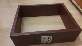
I was thinking to solve the problem of 300B floating 5VDC supply with this schematic that I attached. I'm running 230V 50/60Hz Mains. I made a wood chasis and was thinking about placing aluminum plates on top and bottom if that makes sense? Can you maybe show me more in-depth about that major cause of hum and the central grounding point? Thank you for such an resourceful comment.
Attachments

I may need some more time to research and better analyze that dual 5V supply.
Just look below and see what needs to be checked:
Correct, Dual is required, so that for a stereo chassis, you have individual self bias for each 300B.
You are moving in the right direction.
The issues are:
For 1.25A filament, the secondary should be about 2 times that, or 2.5A rating to keep the transformer from getting hot. AC and DC current ratings for a secondary are not the same.
The shotkey bridge has to be a low voltage drop version.
The IC has to have enough difference between its input voltage to output voltage, or it will not regulate (low drop-out chip).
The IC has to provide much more than 1.25A during power-up, because the filament is cold, and has lower resistance, draws more current cold. If the IC will provide, say 2 Amps, it will eventually warm up the filament, and then the current will drop to the tubes 1.25A. That can work, but if the IC has an automatic 1.5A current limit that may take longer for the filament to heat, an it also depends if it will keep providing 1.5A until the filament warms up.
A 6800uF cap at 50Hz line frequency has 1/(2 x pi x f x C) capacitive reactance, that is
0.47 Ohms.
At 1.25A operational filament current, that is 1.25 x 0.47 = 0.588V peak to peak ripple.
At 2A start-up filament current, that is 0.94V peak to peak.
If the peak voltage from the bridge and the 0.94 is to low for the required voltage at the input to the integrated circuit, versus its output voltage, the IC may drop out.
A larger input capacitance may be required to keep the peak voltage minus the ripple voltage at a level that makes the IC work.
Do not forget to heat sink the ICs.
Parts with real good specs are required to make this work well.
It has to work with the power main voltage when it has at its high level.
But it is harder for it to work when the power mains voltage is at its lowest level.
My mains vary from 117V to 123V. I design the filament supply for 120V.
I use a 6.3V secondary, shotkey diode bridge, and a 22,000 uF cap, a 2 Ohm resistor, and another 22,000 cap in a 'brute force' CRC filament power supply. The ripple is 1 to 2 mV. I do not even have to use the 100 Ohm pot, just two 25 Ohm resistors from the filament ends to the top of the RC self bias network. The transformer filament winding is for up to 3.5A, and has about 6.7V instead of 6.3V, and I adjust the 2 Ohm resistor accordingly for 5V across the filament.
Because there is no IC, dropout can not happen.
This is intrinsically a soft start filament power supply, because of the low resistance of the 300B at power-up, and the 2 Ohm series resistor.
Works for me.
You can use wood sided construction and metal top and bottom plates. Be sure to connect the top and bottom plates together for safety and for hum control.
Last edited:
If the first capacitor does not have enough capacitance, there will be too much ripple to the IC, and the voltage to the IC will drop too low.
The output has to be 5V.
Start with what the peak voltage to the rectifier diodes is.
6.3VAC = 8.8V peak to the rectifier diodes.
A diode bridge has 2 diodes in series for every alternation.
https://www.analog.com/media/en/technical-documentation/data-sheets/108345fh.pdf
You can see the required voltage for the LT-1085 that you picked. It needs at least 6.5V input to get 5V output.
That means the ripple voltage from the first filter cap, must never drop below 6.5V.
You have 8.8V peak, minus two diode voltage drops, and minus the ripple of the first capacitor.
The application sheet below shows a 10uF first cap. I bet you will need at least the 6,800uF first cap that is in your schematic.
That depends on the DCR of your filament winding, and the drop in the diode bridge you have.
The GBU4A bridge you selected has a 1V drop at 2 Amps.
In order to get 1.25A at the IC, the first capacitor draws quite a bit more than 1.25A, it could easily be 2 Amps peak.
The 6.3V secondary provides 8.8V peak. The bridge drops 1V from that, so now 8.8V -1V = 7.8V.
6800uF is 0.47 Ohms. 1.25A through 0.47Ohms drops 0.59V, at the low point of the ripple.
7.8V - 0.59V = 7.21V.
You may have enough margin to get your circuit to work. We can not tell, because we do not know the power mains voltage range, power transformer rated primary voltage, primary DCR, the secondary DCR, etc.
But it appears you have enough margin.
I have similar problems when I use my brute force power supply, I have to estimate some of the figures.
But I always build, test, and adjust the filament supply, before I build the rest of the amp. That way the tubes are tested to warm up properly, before I bring the B+ up.
Last edited:
If its not too late drop the 6SN7 and go to D3As. I just built one and its just amazing. Also I would recommend getting the tentlabs filament supplies. I have 12inch Audio Nirvana Speakers in large boxes, super sensitive. And I can hear a bit of noise up at the speaker but where I sit its quiet. No hassle dialing anything in. Just wire them up and adjust for 5v and never touch again.
The whole amp is not cheap but damn its just amazing. With a good DSD source it makes you grin from ear to ear. its like having a musician sitting on your coffee table with your eyes closed.
Build it!! And take your time and dont skimp on components. You will not regret one cent you spend on this. I would recommend this design. The damping is better than most 300B designs as is the distortion is lower as well. the new reference 300B amplifier
Jeff
6A3sUMMER has covered everything in his usual excellent way, but I wanted to put in a plug for the filament regulators from Rod Coleman and Intact Audio's elegant AC>DC supplies (intact audio), designed to work together. Top recommendation. You will always need two filament voltage windings for two channels.
All good fortune,
Chris
All good fortune,
Chris
6A3sUMMER has covered everything in his usual excellent way, but I wanted to put in a plug for the filament regulators from Rod Coleman and Intact Audio's elegant AC>DC supplies (intact audio), designed to work together. Top recommendation. You will always need two filament voltage windings for two channels.
All good fortune,
Chris
I have all the components and I have some transformers, my only problem is how to put this physical components into my box, like where do I put my capacitors, resistors, transformers, chokes, etc. if anyone could maybe let me know some of their ideas I would be very grateful.
Looking at the galleries of completed projects might be helpful, particularly on the Tubelab forum for TSE II builds. When it is assembled and playing music, it can still be another 80% of the effort required IME. I make it hard for myself by repurposing old enclosures, but the refinement of the final product requires patience in the final assembly.
And there are different ways to skin the cat, so looking at other solutions helps there.
And there are different ways to skin the cat, so looking at other solutions helps there.
- Home
- Amplifiers
- Tubes / Valves
- 300B SET