Found it with the wayback machine.
For the rectifiers I would use a STPSC2H12D high voltage Schottkey....these days....
STPSC2H12D STMicroelectronics | Mouser Nederland
Also I would use a tranformer that could supplu more than 200mA. More than 300mA would be better.
For the rectifiers I would use a STPSC2H12D high voltage Schottkey....these days....
STPSC2H12D STMicroelectronics | Mouser Nederland
Also I would use a tranformer that could supplu more than 200mA. More than 300mA would be better.
Attachments


Bob's only comment on his web page was,
"This was an attempt to get the "magic" sound of my "Darling" SE 1626 amps but with significantly higher power. In any event, the 1626 does make a nice low-mu, high current driver for the 300B. The choice of paralleled 5965/12AV7 in the input stage was mainly driven by pre-existing 9-pin sockets in the amp chassis. So far, this has worked out well."
So you might want to read his page on the Darling here.
There have also been innumerable builds and variations done ofver the years come of which you can probably still find by searching "Darling" together with tube amp or something like that.
In my experience the 1626 is not a great-sounding tube. I know there was a lot of fuss about it many years ago, but I always found it had a nasty bite on the top end. It's not a very linear tube, being made for Class C telegraphy service. A triode-wired 6W6 would be an almost exact drop-in substitute and would sound a whole lot better. Just my two cents.
Bob's only comment on his web page was,
"This was an attempt to get the "magic" sound of my "Darling" SE 1626 amps but with significantly higher power. In any event, the 1626 does make a nice low-mu, high current driver for the 300B. The choice of paralleled 5965/12AV7 in the input stage was mainly driven by pre-existing 9-pin sockets in the amp chassis. So far, this has worked out well."
So you might want to read his page on the Darling here.
There have also been innumerable builds and variations done ofver the years come of which you can probably still find by searching "Darling" together with tube amp or something like that.
Thanks so much for the information
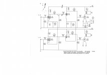
Post #1 Schematic 300B filaments (5V).
Post #2 Schematic 6.3VAC to 300B filaments. (transformer says Both 5V and 6.3V) Wrong.
Use 5VDC for the 300B (to lower the Intermodulation Distortion).
Use individual filament power and individual self bias resistors and individual bypass caps for each 300B.
Use individual self bias for each 5965 input triode (1120 Ohms and individual bypass caps).
Use individual grid stopper resistors (100 Ohms) for each grid.
Maximum grid resistor for 1626 is 10k to 14k (but in fixed bias RF service).
Your audio 1626 application is with self bias, so it is probably OK with 100k or 200k, but maybe not the 470k in your schematic (could that be a cause of harsh sound?).
Last edited:
Yeah the text in the schematic is wrong. I'm sure Bob wired it up correctly though.Post #2 Schematic 6.3VAC to 300B filaments. (transformer says Both 5V and 6.3V) Wrong.
Hi 6A3sUMMER
does individual self bias and bypass cap also require for 1626?
I will try different value for 1626 grid resistor.
Thanks for your advise.
does individual self bias and bypass cap also require for 1626?
I will try different value for 1626 grid resistor.
Thanks for your advise.
Yes, tubes tend to want their own individual bias (self or fixed adjustable).
Double the resistance to 2k for the separate 1625 bias resistors, and bypass each one with its own cap.
Changing from 470k to 200k or 100k will require more capacitance in the coupling cap.
The 22k input plate load should be able to drive a 100k or 200k grid resistor of the next stage.
Most changes in a circuit require some adjustments of the other parts, in this case the larger coupling cap.
Last edited:
Use individual filament power and individual self bias resistors and individual bypass caps for each 300B, that means I need another secondary 5V center tap output from the transformer with bias resistor of 1.2K.
But the power for 300b filament does match between the two schematics???
But the power for 300b filament does match between the two schematics???
Last edited:
Unlike the other tubes in your amp, the 300B has a Direct Heated Filament.
The filament and "cathode" are one and the same.
Having individual self bias for a 300B requires individual filament supplies.
If you are not going to use 5VDC power for the 300B tubes; you have to use 5VAC,
a center tap on the 5V will not allow you to null the hum to a minimum.
You need to use 25 Ohm resistors, and a 25 Ohm pot at the center with the pot wiper (to null hum) going to the self bias resistor and bypass cap.
fil pin 1, 25, 25 pot, 25, fil pin 4. Pot wiper, 1200 Ohms & bypass cap paralleled, and 1200 Ohm and Cap other ends to ground.
With the 25 Ohm pot at hum-nulled position, there still will be some IM (see below).
5V DC power for the filaments is more complex. But it does 2 things:
Reduces hum, and no need to null it out
Reduces intermodulation tones on each music note (100Hz IM for 50Hz mains, and 120Hz IM for 60 Hz mains).
Example of 60Hz AC filaments and 1 kHz music note: 880Hz IM (undesired), 1kHz note (desired), 1120Hz IM (undesired).
440Hz 'A' music note, 60Hz AC mains: 320Hz IM, 440Hz note, 560Hz IM.
Sad but true.
Last edited:
Method 1:
Connect the negative end of the filament and 5VDC supply to the top of the self bias resistor and the Plus lead of the bypass cap. Connect the other ends of the self bias resistor and bypass cap to ground.
Method 2:
Connect two 25 Ohm resistors in series; then across the + and - filament ends (+ and - from the 5VDC). Connect the junction of the two 25 Ohm resistors to the top of the self bias resistor and + of the bypass cap. Connect the other ends of the self bias resistor and bypass cap to ground.
I prefer method 2, but both work.
If there is a little ripple in the 5VDC, method 2 has less hum.
Last edited:
- Status
- Not open for further replies.
- Home
- Amplifiers
- Tubes / Valves
- 300B SE with 1626 driver by Bob Danielak