Someone bought a job lot of 48V PSUs? I hope the lower ones can sink current - or is this a paper exercise that the designer has not actually built?
He has built it. In fact he built quite a few with those psu's.or is this a paper exercise that the designer has not actually built?
Video to his GM70 amp: YouTube
See the stacked psu's in the background.
I can't answer for the designer but here are a few reasons. No power transformers/rectifiers/caps etc needed. Lets say he bought 40 for 2 dollars each. There you have a power supply for 80 bucks.Sorry guys I should be asking why is it design this way.
Last edited:
WARNING … Here's something to consider: whether a string of SMPS has internal hi-pot insulation sufficient to sustain 700+ V from output to … PCB … screws-and-fittings, etc.
I used to build fairly specialized HV supplies for various laser applications. The temptation (which I naïvely gave into) was to string a bunch of smaller, cheaper medium-voltage-secondary transformers together in series, to obtain the 7 to 10 kV I was looking for. Tried it once, and the whole lot of them basically melted down and fissioned.
The insulation wasn't up to the job.
Same goes for using a string of SMPS to get to 700+ volts. Is the internal insulation really up to the job?
Just saying,
GoatGuy ✓
As to the OP's question, “why is it designed like this?”
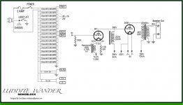
On the one hand it is easy to say: because the designer wanted 750 volts, and didn't really embrace the idea of finding a 550–0–550 volt transformer and a pair of HV rectifier bottles, and the complications of HV rated capacitors (usually strings of lower voltage rated ones… with voltage-sharing bypass resistors), and so on.
On the other hand, perhaps because the SMPS's … even a box of 16 of them … is pretty darn inexpensive. And, the author supposedly having tested them lashed together as per the diagram, has a cheaper-better-more-efficient way to create the HV desired for the 300 B bottle.
________________________________________
As to the circuit, it couldn't be simpler, I'd say. Using a choke load on the first triode is actually a good choice nominally, since it serves as a self-adapting (nearly) constant current source. Back-EMF allows for positive anode voltage excursions that are QUITE a bit above the (lower) B+ supply that it has. Turns the 841 into an almost perfect voltage amplifier. The 300B bottle is doing what it does best. The original author clearly was trying to avoid using capacitors anywhere in the design. They having a mostly-unfounded but oft-repeated reputation for coloring the sonics passing thru them. Like so many things in design, it is just a at-the-wall-of-reason position. Still … the use of the SMPS chain allows the 300B to float above the anode of the 841. Woot!
That's just my take.
I'd also imagine it is a nice amplifier in real life.
Depending on the qualities of the chokes and output transformer.
Just saying,
GoatGuy ✓

I have used this method and it works. It's important not to connect the ground prongs together. Effectively the units are floating. I found I could use insulated 1/4" female spade connectors if I loosened the connector part with a screwdriver to connect to an AC prong. The ground prongs are left unconnected. It's also important to daisy chain your outputs correctly to make sure you don't connect a positive to a positive. There is no need to take the cover off the SMPS units.
I used the push-in connectors as an experiment. I had a bunch left over from installing some LED lights in our kitchen. I attach them with GOOP to the top of the SMPS units.
In my case I have 16 units. Units 1 to 4 provide -196 vdc and 5 - 16 give +576 vdc. I set my ground between units 4 and 5. It's also possible to tap other voltages from your stack provided it is a multiple of 48 volts.
I tried this because I wanted my amps to be lighter weight for health reasons. Yes, it works but it is fiddly. It's much simpler to do the usual transformer, choke, cap arrangement, but heavier.
ray
I'd be a little worried about noise with that many SMPS in a tube amp. Also, for 750 volts, there are easier, cheaper and more elegant ways than this that don't involve buying a 550-0-550 xformer. Like putting a 120:240 and a 120:48 xformer in series and using a voltage doubler.
Me? I'd go for the 550-0-550. Xformers with such high voltages are in lower demand and can be picked up reasonably cheaply.
Me? I'd go for the 550-0-550. Xformers with such high voltages are in lower demand and can be picked up reasonably cheaply.
- Status
- Not open for further replies.
- Home
- Amplifiers
- Tubes / Valves
- 300B Schematic Tutorial