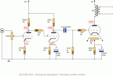
I am working on a JE Labs 300B as shown. I am getting nothing but oscillation from the speaker. When testing B+ voltage I noticed it varied on a regular basis from 424-435 volts. Usually it will stay steady. I have checked everything over and can find no faults. Any ideas?
Attachments
What is the frequency of the oscillation. Does it vary as you adjust the vol control. Is there sufficient decoupling on the power supply.
check heather supply and +B/+B2 psu filter
220K resistor are not safe for WE or like nos 300B
put grid choke the soundwill improve
and the 300B will last very long
also avoid oil cap to 300B grid
a good quality MKP its necessary
i drive my 300B from IT and dht triode 6C4C
220K resistor are not safe for WE or like nos 300B
put grid choke the soundwill improve
and the 300B will last very long
also avoid oil cap to 300B grid
a good quality MKP its necessary
i drive my 300B from IT and dht triode 6C4C
If the 300B is not gassy, then 220k should be OK, because the tube is self biased.
The schematic ground connections, in the order shown, could be a large ground loop.
Just think of all the 300B's signal current flowing through the ground wire on its way to the input tubes cathode bias circuit, and then on to the volume control, and then finally to ground.
Make sure the 300B bias resistor and bypass cap are returning to the negative of the B+ capacitor that feeds the output transformer primary. Make those large currents pass locally, not globally.
Remember, wires are inductors. Wires not only have DC resistance, they have inductive reactance at high frequencies.
Be careful how wires are positioned.
For example if the 300B plate and output transformer primary wires pass by the input and driver tube grids, that might be enough capacitance to cause an oscillation.
Do add a a 1k grid stopper in series to the input grid.
Always connect a load to the output transformer secondary.
Are you sure it is the 300B that is oscillating, and not a previous stage?
If the oscillation is in the hundreds of KHz range or less it is probably a tube oscillation.
If it is above 800KHz, it could be an AM transmitter getting into your input.
What is your input tube?
Is your suppression connected at the tube socket pin?
If the oscillation is in the hundreds of KHz range or less it is probably a tube oscillation.
If it is above 800KHz, it could be an AM transmitter getting into your input.
What is your input tube?
Is your suppression connected at the tube socket pin?
Short the 220k and see if the oscillation is gone. If so, it is in the previous stages.
Yes to another 1k at the first grid.
Yes to another 1k at the first grid.
Last edited:
The driver circuit in this JE design can be at risk of oscillation. The two anode-load resistors are fed from the same point, and so there are two anti-phase currents in the supply wire.
1. For best chance of stability, the wiring to the anode loads must be short, and a good 47µF electrolytic placed near to the anode resistors, with the shortest possible wire to the ground-point near the cathode resistors.
2. Is the driver-tube known good and tested? If there is any mechanical damage to the 6SN7, the driver output can oscillate, even if the circuit is OK.
- Home
- Amplifiers
- Tubes / Valves
- 300B oscillation