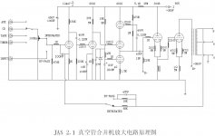
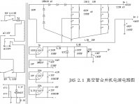
I am repairing an 805 SET amp, driven by a DC 300B, and this is the second time the bias winding for the 300B has gone open in this amp and I'm wondering what could be causing it. It was replaced once by the previous owner, and now it's my turn. It's a dual mono chassis with very robust transformers, very well made JAS 2.1 amp. It's a very simple circuit, I have checked the bridge and zener, both fine, and also ran the bias winding from the good channel to the input of the bridge just to check and it works fine.
So my question is, how much grid current, if any, is drawn by a 300B cathode follower directly coupled to an 805. I'll attach schematics so you can see what is going on.
I have 2 options, I could use the good channels' bias winding for the grid supply for channel 1, or install a dedicated bias supply xfmr for the bad channel, maybe get it big enough to handle both channels if the good one fails some day.
Thanks!
Attachments
Last edited:
The 300B grid might take a little current - but only when the grid is positive with respect to the cathode (filament).
Positive current can only be taken from the bias supply if the 300B cathode-choke pulls the cathode below about -85V or so below the grid, also, and even then, there is over 220K of series resistance between grid and bias supply. So for example, if the choke pulled the cathode to -400V while the grid was driven to +250V, the current would still only be less than 3mA, and to double this current, the cathode choke would need to generate a negative pulse of >1kV.
So I do not think that operational overcurrent caused the transformer failure; and anyway, the 220K grid leak resistor would probably pop before any harmful current could flow in the bias supply.
It might be worth mesuring the 220K grid resistor, and checking that it is really 220K.
I suspect the most likely reason for failure is that the bias winding is not sufficiently insulated from the peak voltage of the main HV winding, and that an overvoltage event caused the bias winding to develop an internal short circuit. It will be wound with thin wire, and a short of this will not blow the fuse.
I would not trust such a transformer - and would certainly never leave it powered on while unattended.
option 2 seems a better option..
as mentioned above, there are enough resistance to the 300b grid circuit to limit the current....
i suspect a bad traffo here...
as mentioned above, there are enough resistance to the 300b grid circuit to limit the current....
i suspect a bad traffo here...
OKay, thanks for the help. I will find a small bias xfmr to fit under the chassis and bias both channels from it, thus relieving damage due to the possible failure of the large xfmr's bias winding. I have installed an NTC inrush limiter and fused both HT rails to safeguard against catastrophic incidents. This is my first amp that has kilovolt supplies so maybe I am going overboard. 🙄
Oh and one other item that may have caused a problem, someone in the past had added another 4 in series, 1000uF caps to each HT rail, which would create a HUGE startup surge so I have removed those, it's back to stock form now. That could have stressed the HT winding, who knows.
Cheers
Oh and one other item that may have caused a problem, someone in the past had added another 4 in series, 1000uF caps to each HT rail, which would create a HUGE startup surge so I have removed those, it's back to stock form now. That could have stressed the HT winding, who knows.
Cheers