Over the years, I got to the "Stage in Life" when I no longer used Interstage transformers.
Right, Wrong, or neither.
Single ended to single ended (Layered, and also Bifilar)
Single ended to push pull
Push pull to push pull
Different winding techniques
Auto transformer phase splitter
Right, Wrong, or neither.
Single ended to single ended (Layered, and also Bifilar)
Single ended to push pull
Push pull to push pull
Different winding techniques
Auto transformer phase splitter
If you want a DHT driver, and a two stage design: EML30A is a nice candidate. I have used it as driver in a GM-70 se. Loaded by a Iso NC-f2 interstage transformer it delivered 100 Vrms with the 2.harmonic about -60 dB.Hello…
Driving a 300b always seems to be a point of discussion, but I can’t seem to find a mature schematic for a 300b driving 300b - any out there?
(I also note that some designers, like Thomas Mayer have also made 211 driving 211).
Ideally I’m looking for a two stage 300b pse/pp amp with interstage transformer and an input sensitivity around 2v or thereabouts.
Very interesting discussion, showing that there are no secrets, just basic knowledge.
To me tube amplifiers are just like apples, the very good ones that sound/taste great have imperfections. The apples that have no imperfections are products.
To me tube amplifiers are just like apples, the very good ones that sound/taste great have imperfections. The apples that have no imperfections are products.
It has been a few years, but I recall having differential probes for each channel. No reason a 100X probe would not work similarly if you watch the probe and scope maximum ratings. AC couple the channels, put them in X-Y mode and look at the lissajous pattern. For identical phase shift between each, one expects a 45 degree straight line (ellipse of eccentricity = 1). If the phase shift differs, the pattern begins to open up into a more familiar ellipse, eventually reaching a circle (eccentricity = 0) at phase shift of 90 degrees. This is a convenient way to sweep frequency with your function generator at the RCA input, and see at each stage along the way how severe the shift becomes.How did you measure phase imbalance on the *SN7 plates? Direct measure with 100X scope probes, one probe for each scope channel, looking at 20 kHz?
At the input transformer secondary (I had used both Tribute and eventually changed to Cinemag), phase shift was perfect. I could sweep from 10 Hz up to 40 kHz and always a perfect straight line on the scope. Magnitude was also very consistent, which is observed by noting the length of the straight line. It just never changed, it was like watching a static image. Although I knew little about the construction of the windings, no input transformer would be bifilar; they are built for high CMRR and often shielded. Therefore, a significant reason for the wonderful performance is actually the low capacitance of the triode grids and 3 inch interconnects. And I would add, similar capacitance on each leg. The load establishes the balance.
For the first interstage, I originally had O-Netics, and later tried Lundahl LL1692A. Wish I had a video of the scope pattern as I swept frequency - it was not only opening up into an ellipse, but it was not a good looking one! One edge of the ellipse looked reasonable, while the other edge was erratic (not a smooth arc). This indicated the presence of not only phase shift, but distortion was well. Based on which IT winding had the problematic stray capacitance, that SN7/7119/ECC99 plate was distorting, and distorting unequally between each polarity. Granted, looking at the IT secondary was poor as well, but for me, I could see the root problem was showing up at the plates. The load consisting of the transformer stray capacitance was simply too much for the triodes. Place the scope in Y-T mode and look at the sine waves on each plate; yep, clear visual distortion. How unfortunate, right? Whereas the input transformer did not burden the preceding driver, the IT was a large nonlinear and unbalanced load for its driver. Even with no load connected to the IT secondary.
I did further experimentation with the Lundahls, which allow a great deal of different winding configurations and turns ratios. Forwards/backwards, step-up/step-down, etc. No matter what configuration chosen, I could never get a lissajous pattern that was tolerable on any rational basis. They were just all over the place. Looking at the 46 grids, one grid was getting supplied with 5VAC, the other with 3VAC due to the phase imbalance. This is not how the stage was designed to operate!
Now, there was some corrective action when considering the end-to-end (differential) performance of the IT stage. Distortion improved, frequency response was better, though you could still see some degree of magnitude variation over frequency sweep. So by the time I get beyond the OPT and to the speaker, some of that problematic behavior gets canceled out. But why knowingly be generating distortion at each stage, hoping your output transformer cancels it out?
My conclusion was to dump the first stage IT and go cap-coupled to the 46. Put in the CCS as the SN7 plate load, and you get one of the lowest distortion circuits obtainable by tubes. Design the gain structure appropriately such that you never run the risk of blocking distortion or grid current, and the first stage is perfected. The amp was listenable at this point. The 46 does a much better job driving the IT than does the SN7, so I hobbled along knowing the amp was compromised. I ran it for a year or so until I discovered the Monolith offering of their bifilar IT. Gave it a try after some grueling rebuild efforts and was thrilled at the behavior. Pretty much behaves identical to the input transformer!
I never bothered to re-try using the Monolith as the SN7 IT, as I was pleased with the cap coupling. Might be an interesting experiment though.

Excellent insight, you do not add a IT especially to color the sound? It a matter of how much. Why would you need a perfect IT in an tube amp?
Multiplying capacitance by input transformer is not a problem, it is just a matter of output impedance of the source.
Here is a hypothetical situation of a standard 600 Ohm source driving a 10Y via 1:4 step-up input transformer. The input capacitance of 10Y (Miller + grid-fiament + stray) is about 80 pF. The input transformer multiplies it 16 times to 1280 pF. The impedance of 1280 pF capacitor at 20 kHz is about 6 K, so 20 kHz will be attenuated 10%, which is practically unnoticeable.
The output impedance of modern sources such as audio card or CD player is about 100-200 Ohms. This value is due to series output resistor whose purpose is to suppress RF oscillation. If this resistor is replaced with an RF choke, the output impedance can be reduced to almost zero because the output impedance of the output op-amp is very low due to negative feedback.
1:4 step-up is a MILD example of input transformer. There are high quality input transformers with ratios of 1:30 and higher and 2 dB frequency range of 20-20,000.
I suppose one could add whatever "device-x" to color the sound if they like.Excellent insight, you do not add a IT especially to color the sound? It a matter of how much. Why would you need a perfect IT in an tube amp?
The general idea for myself is to avoid blocking distortion of a capacitor-coupled topology due to grid current, especially in the output stage. This gives additional headroom, and the ability to drive 15W confidently. Can hit 25W bursts without a hitch.
My frequency response is +/-0.25dB, with 0.01%THD and low IMD out of a design that has zero feedback once it leaves the D/A. Coloration??
Perfect?
Try a frequency sweep
Try a Square Wave
Etc.
"Perfect is the Enemy of Good" - Frank Reagan, "Blue Bloods"
I am into Good, because I do not have Infinite Fund$.
Try a frequency sweep
Try a Square Wave
Etc.
"Perfect is the Enemy of Good" - Frank Reagan, "Blue Bloods"
I am into Good, because I do not have Infinite Fund$.
IT offers several advantages:Excellent insight, you do not add a IT especially to color the sound? It a matter of how much. Why would you need a perfect IT in an tube amp?
1. It allows 2x more efficient use of B+ compared to RC-coupling. This is very important in a driver stage that must deliver high amplitude signal with low distortion.
2. It allows full utilization of stage's gain, which is equal to mu with IT.
3. It eliminates coupling capacitors, which add more coloration than good quality transformers.
4. It provides low DC resistance path from output tube grid to ground, an important safety feature.
5. It allows tweaking gain structure through varying primary-to-secondary ratio.
Last edited:
7. It represents an almost infinite load(horizontal loadline) this translates in lower distortion.
The Lundahls seem to have some sort of internal imbalance when used as ITs. One side starts saturating, which makes me wonder about internal symmetry, despite the external appearance.
Zigzagflux, which current sources (dynamic plate loads) did you find satisfactory? I found the usual ring-of-two transistors had a noticeable grainy coloration, as well as questionable sensitivity to high-voltage transients. But surely there are current sources better suited to HV vacuum tube applications. I sometimes wonder if a dual triode could not be pressed into service as the control element.
I'm asking in the context of the input tube, of course, so it is a high-Z environment with only +/- 15V of swing to deal with.
Last edited:
Lynn,
The amp is chock full of the same boring CCS present all over the DIY web site, attached. DN2540 on the bottom and IXCP10M90S on top. I made up a batch of compact circuit boards with isolated heatsink, and just copy/paste with a few resistor changes as needed. For really high currents, it also has provision for a parallel set of mosfets on top.
I have not experienced any harshness with these, although without the zeners they are prone to failure on startup/shutdown. Keep leads short, avoid parasitics. The 900V rating of the top fet is pretty robust for most designs. So far so good. If it does fail, they are easy to swap out, fortunately.
Practically, it would not be possible for me to build this without sand; each channel requires 4 CCS. Trying to squeeze in tubes for that function just would not work. The amp consists of a single chassis for dual dedicated power supply, a left chassis, and a right chassis. The power supply can barely be lifted by me, and is rectified with 6DE4 diodes. With Coleman regulators for the DHT's, the amount of heat generated by the amp heats up the room significantly. More tubes/heaters? Just can't do it - compromises are inevitable, and I feel comfortable with where I cut back margins. Attached is a capture of the system voltage/current. I can barely run this on a 15A circuit!
The 400V B+ is unregulated, with a volt or two of ripple. The 300V for the driver stage is regulated with 2 x OD3 gas regulators, also fed by the same general CCS between 400V and the gas tubes. The CCS plate loads for the SN7 stage do an excellent job keeping 120Hz out of the first stage. The regulated 300V stage was needed to keep 120Hz ripple out of the driver stage, since it uses no rejection mechanism other than the differential topology. I could see and hear that ripple getting through the driver stage without regulation, especially when the driver stage was required to drive a little 300B grid current.
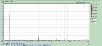
FFTs attached showing the differential signal at the driver stage grids when the amp is driving 1W and 15W. This is the best way I could find to prove out the SN7 stage and CCS behavior. No IMD, no sidebands, nice waterfall, and nearly unmeasureable odd harmonics above the 5th. And the amp sounds like this; really pleasant. It is very easy to continue turning it up every few minutes, until you start to wonder if you are pounding the speakers too hard. At zero signal, you can touch your ear to the speaker and get a barely-there pleasant ocean sound. Thanks to you for the inspiration, and the freedom to tweak as the individual prefers!
The amp is chock full of the same boring CCS present all over the DIY web site, attached. DN2540 on the bottom and IXCP10M90S on top. I made up a batch of compact circuit boards with isolated heatsink, and just copy/paste with a few resistor changes as needed. For really high currents, it also has provision for a parallel set of mosfets on top.
I have not experienced any harshness with these, although without the zeners they are prone to failure on startup/shutdown. Keep leads short, avoid parasitics. The 900V rating of the top fet is pretty robust for most designs. So far so good. If it does fail, they are easy to swap out, fortunately.
Practically, it would not be possible for me to build this without sand; each channel requires 4 CCS. Trying to squeeze in tubes for that function just would not work. The amp consists of a single chassis for dual dedicated power supply, a left chassis, and a right chassis. The power supply can barely be lifted by me, and is rectified with 6DE4 diodes. With Coleman regulators for the DHT's, the amount of heat generated by the amp heats up the room significantly. More tubes/heaters? Just can't do it - compromises are inevitable, and I feel comfortable with where I cut back margins. Attached is a capture of the system voltage/current. I can barely run this on a 15A circuit!
The 400V B+ is unregulated, with a volt or two of ripple. The 300V for the driver stage is regulated with 2 x OD3 gas regulators, also fed by the same general CCS between 400V and the gas tubes. The CCS plate loads for the SN7 stage do an excellent job keeping 120Hz out of the first stage. The regulated 300V stage was needed to keep 120Hz ripple out of the driver stage, since it uses no rejection mechanism other than the differential topology. I could see and hear that ripple getting through the driver stage without regulation, especially when the driver stage was required to drive a little 300B grid current.
FFTs attached showing the differential signal at the driver stage grids when the amp is driving 1W and 15W. This is the best way I could find to prove out the SN7 stage and CCS behavior. No IMD, no sidebands, nice waterfall, and nearly unmeasureable odd harmonics above the 5th. And the amp sounds like this; really pleasant. It is very easy to continue turning it up every few minutes, until you start to wonder if you are pounding the speakers too hard. At zero signal, you can touch your ear to the speaker and get a barely-there pleasant ocean sound. Thanks to you for the inspiration, and the freedom to tweak as the individual prefers!
Attachments

When I used various interstage transformers, almost all of them had these characteristics:
Primary inductance
Distributed capacitance
The leakage inductance between the primary and the secondary
Secondary inductance
Distributed capacitance
With all the consequences of the above factors.
A bi-filar wound interstage I had, practically had zero leakage inductance between the primary and the secondary.
But with the wires side by side, the maximum voltage between the primary and the secondary was limited.
Think of the primary at B+, and the secondary at -60 Volts or more grid bias.
No interstage I used was perfect, but they all sounded good.
filenet, (and other readers)
Thanks!
I call that Fletcher's "Munching" curves, because it looks like somebody took a bite at the bottom out of the extreme frequency ends.
I wonder how many conductors know about Fletcher Munson.
Do they adjust the sound levels of the various instruments at the different frequencies to make up for our imperfect ears.
Double Bass, play FFF starting at measure # 59.
A conductor's "Loudness Compensation" of sorts.
Hey, that clarinetist in the 2nd row is using a # 1-1/2 Reed, he should be using a # 1 Reed for better clarinet sound.
Last edited:
- Home
- Amplifiers
- Tubes / Valves
- 300b drives 300b, with interstage transformer