Hello Guys,
I am working at a DIY from scratch of the 300B Audio Note Kit 1.
In the attached picture and in the practice I saw on other DIY 300B examples all the PCB's are mounted from the top with components oriented toward the bottom of the chassis and heat dissipating and rising toward the components side of the PCS's (which is opposite to the top of the amplifier chassis).
I assume the main reason is that if the PCB's (except the one that has tube sockets on it) are mounted on the bottom of the chassis there will be some wires in between the bottom and top of the chassis and this needs to be avoided?
One idea of mine that I wanted to get your advice (since I bought I chassis that is 114 mm inside height) is to still mount from the top but with longer standoffs (ex 50 - 60 mm) and flip the PCB's (except the one with sockets on it) to have all the components facing the top of the chassis.
I have this in mind for better cooling.
Will this be a good idea?
I am working my CAD model of the chassis cut holes so at this stage I can incorporate any design.
THANKS!
Attachments
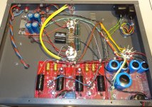
Compared to the picture attached I will have in my design 4 more additional PCB's:
- VU meter PCB for 6E2 tubes
- VU meter DC converter PCB for 6E2 tubes
- VU meter analog PCB
- AC/DC 12v converter
All small PCB's.
Besides these there are the ones in the picture: driver board, PS board and filament board.
- VU meter PCB for 6E2 tubes
- VU meter DC converter PCB for 6E2 tubes
- VU meter analog PCB
- AC/DC 12v converter
All small PCB's.
Besides these there are the ones in the picture: driver board, PS board and filament board.