I am building this amplifier: PDFfiller
Your link goes to some sort of a log-in. Just post the pdf to the forum reply.
jeff
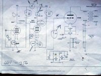
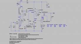
Thanks for the schematic, it helps somewhat. But that scan is hard to read. Can't read the parts values, connections, etc. Can you get a better scan, or re-draw, and post it? It looks like there are a couple of low pass filter capacitors in the input plate and driver plate circuits. Why, is this a 300B Guitar tube amp? Or is it a Hi Fi amp? Or are those capacitor wires just crossing, not connected (can not see enough detail). Since you will now be converted to self bias, you can change the 47k 300B grid resistor to 100k, and ground the other end of that resistor. That will give a better bass frequency response, and a little more gain and lower distortion from the driver stage.
I can not see the details of the pre self bias, or the post self bias circuit. I suggest DC on the 300B filaments. It will eliminate the 2X line frequency intermodulation that occurs on each and every musical tone. With AC filaments, Hum can be adjusted to be low, but the 2X line frequency intermodulation can not be nulled out. I can not see enough of the circuit details to make any other verification of the circuit, or other suggestions.
I can not see the details of the pre self bias, or the post self bias circuit. I suggest DC on the 300B filaments. It will eliminate the 2X line frequency intermodulation that occurs on each and every musical tone. With AC filaments, Hum can be adjusted to be low, but the 2X line frequency intermodulation can not be nulled out. I can not see enough of the circuit details to make any other verification of the circuit, or other suggestions.
Last edited:
300b
I can not get the schematic in a form my computer will use. I took a picture. Sorry. Here is a link to the site Wound Components - Audio Applications It is shown as 300b capacitor coupled se 300b.
I can not get the schematic in a form my computer will use. I took a picture. Sorry. Here is a link to the site Wound Components - Audio Applications It is shown as 300b capacitor coupled se 300b.
I was able to capture that schematic in a more favorable form. I've uploaded it as part of this post.
I read approx. 400 V. on the 300B's plate and 70 mA. of plate current.
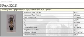
Look here for a chart of 300B operating conditions sets. AFAIK, WE sold 300Bs in the UK branded STC and numbered 4300B.
I read approx. 400 V. on the 300B's plate and 70 mA. of plate current.
Look here for a chart of 300B operating conditions sets. AFAIK, WE sold 300Bs in the UK branded STC and numbered 4300B.
Attachments

...I want to use cathode bias instead of fixed bias. Should the 47k resistor be the same for both?
Read the datasheet!!
electron Tube Data sheets - Search
0.05 megaohm fixed, 0.25 megaohm self-bias
The indicated 47k+pot is just-barely legal in Fixed. For Self you can go much higher, get a little more gain, use something smaller than 0.47u for coupling. Of course power will be down due to voltage-drop in cathode resistor. Unless you jack the B+ to suit.
Attachments
But that's a nice implementation...
woundcomponents.co.uk/300b-docs/SE001CHANNELB.pdf
Why change it....what's wrong with it?
woundcomponents.co.uk/300b-docs/SE001CHANNELB.pdf
Why change it....what's wrong with it?
One possible reason to change an amplifier from fixed-adjustable-bias to self-bias is if you want to do quick tube rolling . . . Insert and Play; instead of insert, adjust, and Play. If you bring your amp to your friends, and you forgot your meter, and he has different 300B brands, you are set to go. That said, there is nothing 'wrong' with the original circuit.
Last edited:
With Auto-bias, increasing the Grid-leak resistor from 47K to (say) 220K, and reducing the grid coupling cap to 0.1µF may be a bigger advantage than it looks, because these little SE amps are certainly susceptible to "blocking distortion" (grid cap charges on signal-peaks, then shifts the bias of the output triode for a while). a smaller cap means lower potential maximum stored charge.
Some modern 300Bs (including Russian) show signs of stress at 400V (A→K); 360-380V is better, if you want to try a range of types.
Some modern 300Bs (including Russian) show signs of stress at 400V (A→K); 360-380V is better, if you want to try a range of types.
410V B+ and ~ a 10V drop through the OPT primary gives ~ 400V Plate.
Self bias of 60V to 70V gives 340V to 330V plate to filament. Otherwise, you can raise the B+ a little bit for more plate to filament voltage.
Go ahead and tube roll, including those modern 300B tubes.
Rod Coleman is right. Blocking distortion is always a problem if you increase the drive all the way to grid current. The tradeoff of the RC time constant is low frequency roll off versus time to recover from blocking distortion.
And some modern tubes will not meet their maximum grid resistance specs, both the fixed bias rating, and the self bias rating. A little on the conservative side helps. That is why I suggested 100k grid resistance, or as Rod said, 220k.
As PRR said: Self bias grid resistor max is 250k. Just be sure to reduce the coupling cap accordingly.
Last edited:
Thank you all for your ideas. I wanted to change to cathode bias because I do not want to bother with adjusting it all the time. I changed over to .22uf caps and 240k grid resistor and things seem to work fine. I used two Torid center tapped transformers. One for 300b and one for signal tubes. When I do not connect the grounds of both circuits I get a big hum. When I connect the grounds of both power supplys together it is quiet but the left channel goes out. I know this is a tough one but any ideas would be appreciated.
...from 47K to (say) 220K, and reducing the grid coupling cap to 0.1µF may be a bigger advantage.... susceptible to "blocking distortion" .... a smaller cap means lower potential maximum stored charge....
Smaller cap, larger resistor, same R-C, same recovery time-constant.
In last decade I checked (an adjusted if it required) my 300B (400V, 70mA) no more than once a year.because I do not want to bother with adjusting it all the time.
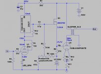
The B+ is 415-416V.
This is a little bit modern version: SiC FET source follower.
Thank you.
- Home
- Amplifiers
- Tubes / Valves
- 300B amplifier