hi,
your amp is a fully complimentary-symmetry from input to output, compared to fotios' single-ended input and VAS.....
you should be able to operate at that levels of rails for testing purposes....instead of rail fuses, you can use 10ohm 1/2 watt resistors just to make sure you dont lose your expensive output trannies in case of miss-wiring..
good luck!!!😀
EWorkshop1708 said:I love big amp forum threads
Me also.
I despise everything it works with a supply level below +/-60Vdc 😀 😀 😀
Also i despise preamps with a supply level below +/-24Vdc. Consequently it is rejected everything builded with ICs. 😀 😀 😀

fotios said:
Me also.
I despise everything it works with a supply level below +/-60Vdc 😀 😀 😀
Also i despise preamps with a supply level below +/-24Vdc. Consequently it is rejected everything builded with ICs. 😀 😀 😀
My MOSFET amps run off +/- 60volts.
My pre amp mixer runs off an ECC83 valve so its supply is 240 volts ! And it bites if you touch it..........
pitty am i, with OPA2134's on my pre's and TLO72 the least! with only
plus/minus 15vdc.......tsk.tsk.....tsk..

plus/minus 15vdc.......tsk.tsk.....tsk..
Hey!
I have all the parts now and started to create the layout. Have some problems with PADS output so the layouts will be screenshots for now. Here they come🙂
Power
Schematics
Soft Start
Schematics
Preamp
Schematics
All comments are welcome🙂
Also have a bit trouble with the main board layout, but this will come tomorrow.
Aq
I have all the parts now and started to create the layout. Have some problems with PADS output so the layouts will be screenshots for now. Here they come🙂
Power
Schematics
An externally hosted image should be here but it was not working when we last tested it.
Soft Start
Schematics
An externally hosted image should be here but it was not working when we last tested it.
Preamp
Schematics
An externally hosted image should be here but it was not working when we last tested it.
All comments are welcome🙂
Also have a bit trouble with the main board layout, but this will come tomorrow.
Aq
Your pcb needs more tidying-up. Some tracks can be shortest. Also you may avoid square pads. Change them by using the library editor of your cad software. Avoid the 90 deg. corners on the tracks because they are nice peaks for electrons concentration thus causing unwanted parasitic capacitances. So you may first mitter all corners in 45 deg and second if it is possible round each one corner. I think all softwares can be do this.
A meaningfull remark also (as nigel points out also) it is the wrong take point of 0V. Usually you need one cable for the amplifier board and another one for the black binding post. Place this point in the middle of the reservoir capacitors 0V track and solder twisted the two cables in this point. Unless you will have buzz noise.
Fotios
Andy L. Francis said:Nice design Fotios! 😉
How high is your slew rate?
Hi Andy
The voltage across a capacitor (Vc) charged with a constant current :
Vc=(Ic/C)t
With a current mirror "load" for the LTP, the full LTP tail current (Itail) is avaliable for charging Cdom when the LTP is overdriven.
So Itail = VbeQ4/R3 = 0.66V/220 = 3mA.
The slew rate therefore = 1E-6(Itail/Cdom) V/us.
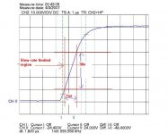
=1uS(.003mA*100pF) = 30V/us
This is nicely confirmed in Figure 4 provided by Fotios.
Cheers,
Glen
G.Kleinschmidt said:
Hi Andy
The voltage across a capacitor (Vc) charged with a constant current :
Vc=(Ic/C)t
With a current mirror "load" for the LTP, the full LTP tail current (Itail) is avaliable for charging Cdom when the LTP is overdriven.
So Itail = VbeQ4/R3 = 0.66V/220 = 3mA.
The slew rate therefore = 1E-6(Itail/Cdom) V/us.
=1uS(.003mA*100pF) = 30V/us
This is nicely confirmed in Figure 4 provided by Fotios.
Cheers,
Glen
As i said in my 71 post these measurements taken by feeding the amplifier with squares from a medium quality generator. Its minimum rise time is 100nsec. You may take into account this.
I know, you are very good in mathematics instead me in geometrical approximation of measurements. In reality your calculation it is approximate and does not gives accurate results. I know very well this from my expertise in practice with big power projects. I know also that some constructors, for an average rise time of 1,8ìsec, they give a slew rate from 80 to 120 V/ìsec and this is fake. On the contrary, many serious constructors for their amplifiers with supplies from +/-80V and above have a fixed rise time of 1,8ìsec and they give a slew rate about 40V/ìsec, and finally a frequency response (this is what we have to examine from the slew rate or the rise time measurement) with a tilt which starts from 50KHz and drops down to -3dB at 100 KHz. This is the true.
Many times i tried to examine the slew rate from the rise time curve but the results have shown that the relation between rise time and slew rate it is not linear as the gain of output increased up to supply rails limits (a dangerous progression by using squares of 10 to 20KHz because we can't see easily the clipping when occurs). Then, i decided the evaluation of the rise time only.
Because the term slew rate it is by far most known in the folks (instead the rise time only in the designers) we have the duty to clarify in them that a slew rate of 40V/ìsec does not says nothing about the transient response or the frequency response of these big power projects. Maybe in small power projects (bellow 100Wrms/8Ù) slew rate it is meaningfull, but i don't know this because in all of my life i deal only with projects from +/-60Vdc supplies and above.
All above mentioned according to my humble opinion and to my expertise for 25 years with these big projects both in design and in testing and measurements and practical implementation and service on the workbench.
As for my project, i believe that it has a slew rate around 40V/ìsec in half swing and above (by estimating the curve and the given time lag of 100nsec of generator) and more than 50V/ìsec in full output swing. We must not forget that this project it is implemented with bipolars entirely (concretelly with the beast 2N5401-5551s which haven't a so good beta instead are the most rugged devices in such high supply conditions) and not fets. Again maybe you wonder, why OnSemi and not Toshiba? Because OnSemis are rated at 500mA Ic instead Toshibas at 100mA Ic and the Ic it is derated perpendicularly according to Vce increasing.
I have to reffer one more thing about the tail current of LTP for this scheme of input stage and with this concrete supply level. Any increasing above 3mA it does not offers any increasing in rise time. I tried also R3=120Ù thus Ic=6mA but nothing changed except the overheating of LTP. Also a Cdom below 100pF in VAS presented overshoot in signal. This amplifier it is locked by its scheme at 1,8ìsec rise time minimum. It does not claim any award in high frequency response because it is not designed for this (don't forget that it is a PA project). On the contrary, it is designed primarilly for the better as possible transient response at low frequencies. And the success it is obvious from the curves quoted in 100Hz and 20Hz. In this point i tried to turn the view of raitraak because he build a subwoofer amplifier. The 7 pairs of output devices it is not for sustaining the load current. I have many tricks in the protection computer to operate this amplifier with only 4 pairs of output devices down to 1Ù without problem. The reason of the multiple output devices, it is to drop down the output impedance of amplifier. This is what the squares of 100 and 20Hz during the 50% duty cycle presented straight (and not concave) with small amount of tilt. This is a secure visual estimation of the steep and powerfull bass reproduction of this amplifier.
I have heared (rather i felt in my stomach and in my liver) a PA band pass loudspeaker with four 15" speakers of 350Wrms/8Ù each, driven from this amplifier to touch frequencies down to 35Hz!
Regards
Fotios
fotios said:
As i said in my 71 post these measurements taken by feeding the amplifier with squares from a medium quality generator. Its minimum rise time is 100nsec. You may take into account this.
I know, you are very good in mathematics instead me in geometrical approximation of measurements. In reality your calculation it is approximate and does not gives accurate results. I know very well this from my expertise in practice with big power projects. I know also that some constructors, for an average rise time of 1,8ìsec, they give a slew rate from 80 to 120 V/ìsec and this is fake. On the contrary, many serious constructors for their amplifiers with supplies from +/-80V and above have a fixed rise time of 1,8ìsec and they give a slew rate about 40V/ìsec, and finally a frequency response (this is what we have to examine from the slew rate or the rise time measurement) with a tilt which starts from 50KHz and drops down to -3dB at 100 KHz. This is the true.
Dude, the calculation is simple and straight forward and is a best case approximation! I didn't take into account the base currents that the VAS buffer and current mirror transistors steal from Cdom, but the value is so small its impact on the final calculated result is negligible. The amplifier simply cannot slew any faster than the tail current to the long tail input pair can charge Cdom. Period!
The 100nS rise time of your signal generator is more than enough cause slew rate limiting (it's more than an order of magnitude faster than the rise time of your amplifier) and your measured results (figure 4 - clarified further in the attachment below) show a slew rate (without surprise) of exactly the calculated value of 30V/us!
How much more accurate would you like it? 😀
None of this is intended to be a criticism, BTW. Please don't take it the wrong way.
Cheers,
Glen
Attachments
BTW, if you would like to make your amp slew 60V/uS instead of 30V/us, then simply change the current setting resistor for the LTP current source from 220 ohms 10 110 ohms.
To make it slew even faster again, simply increase the emitter degeneration resistors for the LTP to lower the open loop gain and the unity loop gain frequency. Then bring the unity loop gain frequency back to out the original value by decresing the value of Cdom.
Cheers,
Glen
To make it slew even faster again, simply increase the emitter degeneration resistors for the LTP to lower the open loop gain and the unity loop gain frequency. Then bring the unity loop gain frequency back to out the original value by decresing the value of Cdom.
Cheers,
Glen
G.Kleinschmidt said:BTW, if you would like to make your amp slew 60V/uS instead of 30V/us, then simply change the current setting resistor for the LTP current source from 220 ohms 10 110 ohms.
To make it slew even faster again, simply increase the emitter degeneration resistors for the LTP to lower the open loop gain and the unity loop gain frequency. Then bring the unity loop gain frequency back to out the original value by decresing the value of Cdom.
Cheers,
Glen
I have to reffer one more thing about the tail current of LTP for this scheme of input stage and with this concrete supply level. Any increasing above 3mA it does not offers any increasing in rise time. I tried also R3=120Ù thus Ic=6mA but nothing changed except the overheating of LTP. Also a Cdom below 100pF in VAS presented overshoot in signal. This amplifier it is locked by its scheme at 1,8ìsec rise time minimum.
fotios said:
I have to reffer one more thing about the tail current of LTP for this scheme of input stage and with this concrete supply level. Any increasing above 3mA it does not offers any increasing in rise time. I tried also R3=120Ù thus Ic=6mA but nothing changed except the overheating of LTP. Also a Cdom below 100pF in VAS presented overshoot in signal. This amplifier it is locked by its scheme at 1,8ìsec rise time minimum.
Like I said, you have to increase the values of the LTP emitter degeneration resistors (by the correct amount) to retain the same unity loop gain frequency, phase margin and stability when reducing Cdom.
I'm surprised that you could not get the amplifier to slew greater than 30V/us by increasing the tail current.
Cheers,
Glen
G.Kleinschmidt said:BTW, if you would like to make your amp slew 60V/uS instead of 30V/us, then simply change the current setting resistor for the LTP current source from 220 ohms 10 110 ohms.
To make it slew even faster again, simply increase the emitter degeneration resistors for the LTP to lower the open loop gain and the unity loop gain frequency. Then bring the unity loop gain frequency back to out the original value by decresing the value of Cdom.
Cheers,
Glen
With 2N5401-5551 in input stage and taking into account the +/-82Vdc supply level i believe that this amplifier can't exceed a slew rate above 40V/ìsec, by no way, and primarily to remain stable and safe during amplification. I tried some of your propositions but in the practice the limiter of the protection computer came into activation when the output reached the half of full output swing.
Dude i have examined this project up to death.
One thing the calculations on the paper, and other thing their transfer in practical implementation.
This weekend in the 24 Le Mans hours race, Peugeots was faster from Audis by 5sec per lap (because Audi=670HP and Peugeot=700HP) and therefore was the dominators for victory. Finally winner proved an Audi mainly due to its fewer and faster pit stops (only tires more often for Audis and not because they were thirsty fuels such Peugeots due to their 700HP engine).
What is the lesson? The speed and the duration (or durability if you prefer) should be kept in equilibrium.
Hey Glen, nothing wrong with your mentioned, i am not so crazy to take it as criticism. Instead i respect your knoweledge and i am happy when i talk with you.
Fotios
fotios said:
I tried some of your propositions but in the practice the limiter of the protection computer came into activation when the output reached the half of full output swing.
Hey?
G.Kleinschmidt said:
Like I said, you have to increase the values of the LTP emitter degeneration resistors (by the correct amount) to retain the same unity loop gain frequency, phase margin and stability when reducing Cdom.
I'm surprised that you could not get the amplifier to slew greater than 30V/us by increasing the tail current.
Cheers,
Glen
Glen
Sincerelly in such type projects as PA amplifiers a slewing of 40V/ìsec it is more than enough. My choice was clearly from tactical view and not from a crazy for speed.
I have builded a prototype with the same architecture at +/-60Vdc supply level. In this i changed all OnSemi with Toshiba except the 4 output pairs which are MJL21XXX and this time with 6mA tail current i have achived a rise time of 1,25ìsec without changing the value of degeneration resistors. Also i changed all caps with silver mica, polypropylene and ECA Panasonic. I have this amplifier in my house for personal use only. The open loop gain changed due to superb quality of parts used this time. In closed loop i haven't change nothing, it is exactly the same values as the PA amplifier. That is the secret.
Fotios
fotios said:
Glen
Sincerelly in such type projects as PA amplifiers a slewing of 40V/ìsec it is more than enough.[ /B]
Hey, I don't disagree, but I would have thought that that triple EF output stage should be able to slew greater than 30V/us with a ~20mA standing VAS current 😕 (I wonder how much input capacitance those predriver transistors have - the data sheets say nothing about capacitances).
I've done greater than that with multiple parallel MJL21193/MJL21194 pairs with another pair of the same devices as drivers in a double EF! My standing VAS current was higher though, with parallel MJE340/MJE350's for the VAS and VAS current source.
Cheers,
Glen
G.Kleinschmidt said:
Hey, I don't disagree, but I would have thought that that triple EF output stage should be able to slew greater than 30V/us with a ~20mA standing VAS current 😕 (I wonder how much input capacitance those predriver transistors have - the data sheets say nothing about capacitances).
I've done greater than that with multiple parallel MJL21193/MJL21194 pairs with another pair of the same devices as drivers in a double EF! My standing VAS current was higher though, with parallel MJE340/MJE350's for the VAS and VAS current source.
Cheers,
Glen
From curiosity; how much it is the slew rate of your project that you refer here?
Fotios
- Status
- Not open for further replies.
- Home
- Amplifiers
- Solid State
- 300 Watt Amp