Hi guys. I present the configurations of amplifiers with more realistic models of pre-output transistors.
Attachments
-
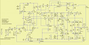 PA-50 BC547 LME49860.jpg151.2 KB · Views: 397
 -
 PA-50 LT1215.jpg120 KB · Views: 391
 -
 PA-50 2JSK170 LME49860.jpg121.3 KB · Views: 373
 -
 PA-50 LT1468 lt215.jpg122 KB · Views: 420
 -
PA-20 LT1468 LT1122.asc10.4 KB · Views: 104
-
PA-20 2jsk170 LT1215.asc12.5 KB · Views: 94
-
PA-50 BC547 LME49860.asc18.8 KB · Views: 92
-
PA-50 2JSK170 LME49860.asc15.6 KB · Views: 117
-
PA-50 LT1468 lt215.asc12.4 KB · Views: 100
-
PA-50 LT1215.asc12 KB · Views: 95
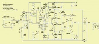
Hi everybody. I imagine another amplifier that gives almost 0% distortion in the simulator.
Attachments
-
 AMP-50 LT1468.jpg237.4 KB · Views: 234
 -
AMP-55 3bk ne5532.asc22.1 KB · Views: 92
-
AMP-55 3bk LT1468.asc22.1 KB · Views: 74
-
AMP-55 3bk LT1122.asc22.1 KB · Views: 78
-
AMP-55 3bk LT1022.asc22.1 KB · Views: 81
-
AMP-55 3bk lt1056.asc22.1 KB · Views: 84
-
AMP-55 3bk lt1058.asc22.1 KB · Views: 78
-
AMP-55 3bk TL071.asc22.1 KB · Views: 89
-
AMP-55 3bk LM318.asc22.1 KB · Views: 84
-
AMP-55 3bk AD825.asc22.1 KB · Views: 84
-
AMP-55 OPA134.asc22.1 KB · Views: 90
As far as I know, you can't prove that something does not exist. Perhaps your instrumentation needs repair.Hi everybody. I imagine another amplifier that gives almost 0% distortion in the simulator.
Hi!Hi everybody. I imagine another amplifier that gives almost 0% distortion in the simulator.
in order:
amplification only 16dB, ok
there is no damping in the C27 integrator, C25 C26 - such a gigantic capacitance! denomination in itegrator, seriously?
the integrator itself is non-inverting and is included in the open input of the circuit - this is a solution of dubious practical quality.
Q10Q11 from the presence of the L1 coil must be selected with a minimum gain error and also glue the cases together.
R15 is connected to the power bus through a weak RC circuit, which means that it is necessary to stabilize the power supply of the entire preliminary part.
Q6 will work in a very loaded mode in terms of power, it will most likely fail first in the circuit.
for the effectiveness of the 2-pole correction C11C12, the input resistance of the cascade VAS is not enough for you.
result: the simulator works, the scheme needs to be improved taking into account the specifics of practical implementation.
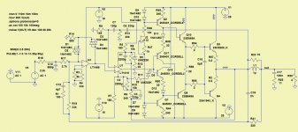
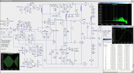
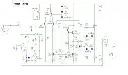
Hello. The schemes previously presented do not work well when clipping.
This scheme is better.
OPA2134 is used.
I think to use non-polar capacitors for the integrator. I will choose with the minimum leakage current.
There is a sufficient amount of 10 uf/35 V with a leakage resistance of more than 20Mom.
What is wrong with such an integrator, what other suggestions are there?
The voltage amplifier will be powered by the LM317, LM337 stabilizers in the TO220 package.
The power transformer is a standard 2*18 V.
33-35 V to supply the voltage amplifier will be obtained by a voltage multiplier.
Attachments
-
 AMP-50_OPA2134_2VK.jpg446.3 KB · Views: 205
 -
AMP-50_OPA2134_2vk.asc26.3 KB · Views: 90
-
AMP-50_OPA2134_3vk.asc26.4 KB · Views: 89
-
AMP-50_LT1468_ 2vk.asc25.3 KB · Views: 80
-
AMP-50_LT1512_ 3vk.asc26.4 KB · Views: 71
-
AMP-50_LT1215_ 2vk.asc25.3 KB · Views: 94
-
AMP-50_LT1468_ 3vk.asc26.4 KB · Views: 84
Can you tell me who is the real author of these schemes? because your compilations are not very logical, i.e. you are not the author of the schemes.Hello. The schemes previously presented do not work well when clipping.
This scheme is better.
if we take only the transistor part, then the input differential stage cannot even balance the operating point, which is why there is a servo integrator.
10uf also a big value.I think to use non-polar capacitors for the integrator. I will choose with the minimum leakage current.
There is a sufficient amount of 10 uf/35 V with a leakage resistance of more than 20Mom.
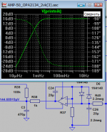
I am the author of the diagrams. There are commentators on another forum - do it differently, add another differential cascade, change the correction. I made a version with changes and posted it. I haven't checked clipping. A more complex scheme turned out to be worse.
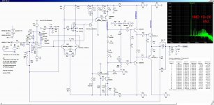
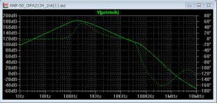
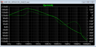
Below graphs of open loop gain with 20uF and 1uF integrator. Probably enough and 1 uF.
Below graphs of open loop gain with 20uF and 1uF integrator. Probably enough and 1 uF.
Attachments
The unbalance voltage of the differential stage will not affect the operating point in any way. The output voltage of this amplifier depends only on the input bias voltage and the op-amp multiplied by the gain of the entire feedback amplifier.
you are not the author of these circuits, you are the author of compilations of other people's circuit solutions, because I see solutions that you can hardly think of on your own or understand their purpose, because you can’t even organize a servo integrator so that it does not affect the amplitude-frequency characteristic of the open loop amplifier, and at the same time has sufficient speed with a minimum leakage current in the integrator’s time constant circuit - this is important for the quality of audio sound ... I will not specify the rest of the nuances, because to. with the growth of experience, many solutions will be basic, now they are not there, tomorrow there may already be a different topology, and so on endlessly...I am the author of the diagrams.
ask how it is right on the forum where you took the circuit solutions, obviously there is a real author.
and decide already on the topology you want to develop, without modeling it is very difficult to comment on something ...

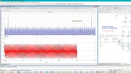
One of the best indicators for a sim regards "nasty" frequencies for IMD. The kind of frequencies advertisers never use because even laymen exposed to the graphs would start thinking "what's the "blue grass" about? One set is 950 Hz and 11.5 KHz, equal amplitude. Applied to a well known textbook amp from the Microcap lib, the distance between every IMD product is 50 Hz. Post yours for comparison 😉
Attachments
I am the author of the diagrams. You can check here: https://uberidee.getbb.ru/viewtopic.php?f=12&t=11.you are not the author of these circuits, you are the author of compilations of other people's circuit solutions, because I see solutions that you can hardly think of on your own or understand their purpose, because you can’t even organize a servo integrator so that it does not affect the amplitude-frequency characteristic of the open loop amplifier, and at the same time has sufficient speed with a minimum leakage current in the integrator’s time constant circuit - this is important for the quality of audio sound ... I will not specify the rest of the nuances, because to. with the growth of experience, many solutions will be basic, now they are not there, tomorrow there may already be a different topology, and so on endlessly...
ask how it is right on the forum where you took the circuit solutions, obviously there is a real author.
and decide already on the topology you want to develop, without modeling it is very difficult to comment on something ...
I took the research on correction and topology from here: https://www.diyaudio.com/community/attachments/omicron-one-channel-schematic-png.1063085/
You don't have to be such a snob. You even put 2000uF into your amplifier into the integrator.
Attachments

oh, I see that there (by link) is someone sanely commenting, and in fact helping.I am the author of the diagrams. You can check here: https://uberidee.getbb.ru/viewtopic.php?f=12&t=11.
very similar to the author of the one who comments on the previous link)))I took the research on correction and topology from here: https://www.diyaudio.com/community/attachments/omicron-one-channel-schematic-png.1063085/
of course, this is a model (that is, both the first and second options, course, were not practically implemented) , in model this capacitor blocked the influence of the integrator on the readings of the amplitude-frequency characteristic, in fact it remained in the finished product, it is separated by resistances and damped, in the integrator itself the capacitor costs 1 microfarad, and at the same time the amplitude-frequency characteristic (open loop) does not humpbacked as in those attachments that you posted earlier..... You even put 2000uF into your amplifier into the integrator.
If you knew for sure that your servo does not affect the frequency response (open loop), then there would be no integrator even in the model, because the composite version, and even the diffcascade in the second block, kept the operating point for the usual analysis.
Last edited:
Zhukovsky approved the values of C24C26 at 20 microfarads in a servo integrator?I've made changes. Now there is no hump.
He hasn't approved it yet. Possible values are 10.2 Mohm, 2.2 uf.
It will be enough 10 uf, 2.2 Mohm, similar to RC.
It will be enough 10 uf, 2.2 Mohm, similar to RC.
10 Megaohm is a very large resistance, in practice it is divided into two consecutive 5.1 Megaohm.He hasn't approved it yet. Possible values are 10.2 Mohm, 2.2 uf.
10 microfarads is also not suitable, it is best to use a RCR filter after the integrator, in fact, as you did, it is only necessary to dampen C so that there is no hump ...It will be enough 10 uf, 2.2 Mohm, similar to RC.
The departure from the triple in the output stage (Locanti triple) is not logical, the deuce in the output stage has a stronger influence of the randomness of the load impedance on its input resistance, in this case it is necessary to maximize the pole of the amplitude-frequency characteristic of the open loop ...
pleasetriple in the output stage
Attachments

- Home
- Amplifiers
- Solid State
- 30 watt composite amplifier with 0% distortions.