
We have all simulated 0......0% amplifiers, but that's spice fantasy mostly. Real effects, third or higher order are not taken into account properly in sim, and physical effects like induction will play a major role in a real implementation.
What is certain is that achieving 0.0% in reality requires much better performance than in sim, but even a spotless sim design won't achieve its target in reality, even if the physical realisation is ideal, free from induction, parasitic resistance, etc.
That said, aiming for a negligible distortion is certainly commendable, provided you don't compromise on other aspects.
IMO, you need to make it without resistors or semiconductorsHi guys. I suggest an amplifier with 0% distortion. It remains only to make the board correctly.
If there is a number on slew rate, means there will be some distortion.
Only passive amplifier, e.g. a bare wire will not produce distortion.
Only passive amplifier, e.g. a bare wire will not produce distortion.
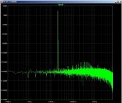
Having produced sims with "about zero" distortion I suspected "something wrong" not only because of the physics involved, subjective reports, but also the likelihood that certain sounds can have an influence at a very low level (IOW subconsciously, affecting mood) because (during evolution) it could signify extreme danger. So I flogged memory about how long ago we wrote simple proggies for mixer performance. For audio, running 950 Hz and 11.5 KHz suggests the usual distortion tests omit something. Pics mention results at 1.9 & 2.3k but the new frequencies show a "grass floor" that when considered "in phase", is higher than the traditionally simmed values.


I think theoritically the Slew rate should be infinity in case of 0% distortion design. Seems impossible.
Once you get past a certain point in amplifier design/construction the distortion is no longer dominated by improvements to the circuit topology or components. It’s dominated by implementation - IOW, how well your implementation matches what you actually tried to build (or simulate). In the RF world where I work this is especially true.We have all simulated 0......0% amplifiers, but that's spice fantasy mostly. Real effects, third or higher order are not taken into account properly in sim, and physical effects like induction will play a major role in a real implementation.
And always remember that models are worth approximately what you PAY for them. Anything obtained for free may have errors or omissions. Might be pretty good, but simulating that low a distortion figure is well within the noise of the models themselves. Want a model that will give you a lower noise floor? Typically you PAY someone to make a suite of measurements and extract a custom model with carefully tweaked code.
That amplifier was designed (including a proper PCB), built and successfully tested half a year ago - see my topic on Omicron. I can assure you that the actual hardware works exactly as simulated, with vanishing distortion (see distortion measurements), and sounds immaculate.I suggest an amplifier with 0% distortion. It remains only to make the board correctly.
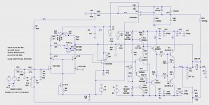
We tested a full diamond buffer like that printnik simulated, but found its benefits marginal compared to a simple push-pull emitter fiollower. By the way, in TS's schematic, J2 may be at risk, as it has almost 50V applied across it, and not all small JFETs are rated for that voltage.
In this particular topology, the maximum output amplitude is limited by opamps (the diamond buffer has unity gain). Because of this, it is ideal for headphones but doesn't scale well for speakers. For example, the LT1468 from the simulation above has the output swing of +/-12.8V, which at best gives you about 40W peak, or 20W RMS into a 4 ohm load - but not 30W as claimed.
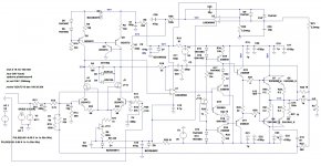
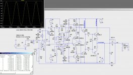
Here is the schematic of Omicron, sans protection and output filter:

Last edited:
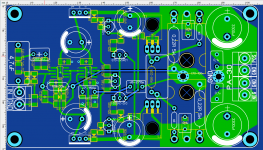
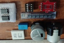
Hi, Astaro. I started drawing the PCB (Not SMD), then I simplified the input scheme, current amplifier for 5404,5551. It is necessary to use stabilizers LM317, 337 (TO-92)
Attachments
-
 PA-50 BC547 LME49860.jpg278.1 KB · Views: 529
 -
 PA-50 2JSK170 LME49860.jpg223.3 KB · Views: 506
 -
LME49860.zip3.4 KB · Views: 115
-
PA-50 2JSK170 LME49860.asc15.3 KB · Views: 102
-
PA-50 BC547 LME49860.asc19.6 KB · Views: 140
-
PA-20 2jsk170 LT1215.asc12.4 KB · Views: 129
-
PA-50.zip37.9 KB · Views: 133
-
 PA-40 LT1468.jpg181.9 KB · Views: 436
 -
PA-40 LT1468.asc12.3 KB · Views: 120
-
 IMG_20221003_105540.jpg274 KB · Views: 477
Here, as it were, there is nothing to be surprised at, this is a stationary mode of simulated distortion, the sensitivity of the circuit is not significant 16.4 dB, progressive correction with an anti-clip circuit, composite topology, Negative feedback covers all non-linear elements of the circuit, including the output inductor - this means significant NFB depth at a frequency of 20 kHz, i.e. essentially a super-linear amplifier.We have all simulated 0......0% amplifiers, but that's spice fantasy mostly. Real effects, third or higher order are not taken into account properly in sim, and physical effects like induction will play a major role in a real implementation.
this does not work here, the speed will be limited by the input filter of the high-frequency spectrum. If it is 10-15 V/uS, then this will be enough.I think theoritically the Slew rate should be infinity in case of 0% distortion design. Seems impossible.
Two things there: in general the Zobel inductor is not included in the GNFB, because of phase-shift issues at higher frequencies. One could build a two-pole fix around that inductor, but that's normally not necessary since this inductor is in the 1~2µH range, low Q and can be air-cored = zero non-linearity.Negative feedback covers all non-linear elements of the circuit, including the output inductor
The real induction problem is caused by class B currents emanating from output devices. Anything in the vicinity of these tracks will be affected: other tracks obviously, including the feedback one, but also components, passive and active
Agreed: SR is like a clipping limit, but dynamic rather than static, and as long as the program does not flirt too closely with the limit, it will have no effect.this does not work here, the speed will be limited by the input filter of the high-frequency spectrum. If it is 10-15 V/uS, then this will be enough.
Some topologies may have a "soft" behaviour regarding SR, comparable to soft clipping, but regular semiconductor topologies tend to have a relatively sharp, well-defined limit
What a good comment. Already redone. Named the file incorrectly. It was right to call it PA-50 lt1215.ascTwo things there: in general the Zobel inductor is not included in the GNFB, because of phase-shift issues at higher frequencies. One could build a two-pole fix around that inductor, but that's normally not necessary since this inductor is in the 1~2µH range, low Q and can be air-cored = zero non-linearity.
The real induction problem is caused by class B currents emanating from output devices. Anything in the vicinity of these tracks will be affected: other tracks obviously, including the feedback one, but also components, passive and active
Agreed: SR is like a clipping limit, but dynamic rather than static, and as long as the program does not flirt too closely with the limit, it will have no effect.
Some topologies may have a "soft" behaviour regarding SR, comparable to soft clipping, but regular semiconductor topologies tend to have a relatively sharp, well-defined limit
Attachments
There would be no audible benefit to having a 0% distortion amplifier over having, say, one with 0.05% of a similar type of distortion. Ear will not pick that up with music program material. It's possible to get very close to 0% distortion, though, and for laboratory work, that may be useful. For living room music listening, not so much.
Missing the point. People on here design low ppm amplifiers for the fun of it. No audible advantage required, just the challenge.
"Would be" means you have not tried it yourself. Try it - it is an interesting experience, and you may be surprised. Just make sure that the distortion actually measures low across the whole audio range of frequencies, not just at 1kHz.would be no audible benefit to having a 0% distortion amplifier over having, say, one with 0.05% of a similar type of distortion.
- Home
- Amplifiers
- Solid State
- 30 watt composite amplifier with 0% distortions.