Looking for some help with a 3 way passive crossover design. Many years ago, when I was a bachelor... I built a 3 way speaker with an active crossover between the mid/woofer. Today, the speakers are sitting in my garage. Unless you all know something that I don't, active crossovers with multiple amps - while great in theory - are not practical in real life. Input sources + pre-amp + active crossover + multiple power amplifiers - if done right = $$$$ + space and not = WAF... I just want to have a pair of speakers using these drivers that I can move without a forklift and power with a Stereo receiver.
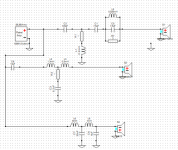
I know the woofer and mid are not ideal pairs for a passive design, but we should be able to make it work. I downloaded X-sim and have cobbled together something that appears to be reasonably flat... I copied the tweet/mid crossover from "The Poor Man Strad" which uses the same mid and a similar tweeter (27TFFC v. my 27TDFC) - and it looks really good... (I think)
A few things I'm unsure of:
1. I used frd and zma files from traces of manufacturers spec sheets. I know I'm supposed to measure them in box, etc... but looking for input on whether that is a nice-to-do or a need-to-do. Generally, I'm planning sealed cabinets. For the mid, Seas states the enclosure that was used for the measurements, so I could replicate that one.
2. Baffle design - I know it matters, but will it have a substantive impact or a minor impact on the output?
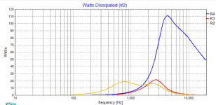
3. The resistor R4 seems to have huge power (110W) dissipation... is that accurate for real world conditions (ie. not a steady state sine wave at the peak power frequency of 4kHz)
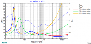
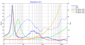
3 b. System impedance above 1kHz gets very low... is that OK?
4. I haven't measured Z offset... is there a typical number which is 'close enough'?
5. Phase... I know X sim accounts for phasing in the freq resp, but not sure if there is more to it than this...
6. I don't know what I don't know - am I missing anything else?
Thank you kindly to all the brilliant minds out there.
I know the woofer and mid are not ideal pairs for a passive design, but we should be able to make it work. I downloaded X-sim and have cobbled together something that appears to be reasonably flat... I copied the tweet/mid crossover from "The Poor Man Strad" which uses the same mid and a similar tweeter (27TFFC v. my 27TDFC) - and it looks really good... (I think)
A few things I'm unsure of:
1. I used frd and zma files from traces of manufacturers spec sheets. I know I'm supposed to measure them in box, etc... but looking for input on whether that is a nice-to-do or a need-to-do. Generally, I'm planning sealed cabinets. For the mid, Seas states the enclosure that was used for the measurements, so I could replicate that one.
2. Baffle design - I know it matters, but will it have a substantive impact or a minor impact on the output?
3. The resistor R4 seems to have huge power (110W) dissipation... is that accurate for real world conditions (ie. not a steady state sine wave at the peak power frequency of 4kHz)
3 b. System impedance above 1kHz gets very low... is that OK?
4. I haven't measured Z offset... is there a typical number which is 'close enough'?
5. Phase... I know X sim accounts for phasing in the freq resp, but not sure if there is more to it than this...
6. I don't know what I don't know - am I missing anything else?
Thank you kindly to all the brilliant minds out there.
Attachments
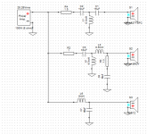
Here's another version based on the current mid/tweet crossover.
A few challenges:
1. When I modelled the crossover as-is, there were two issues: 1. the SPL fell off by a few dB with the tweeter, then it was peaking by about 5dB at 12.5kHz, so I removed the series resistor and added a notch filter to tame the peak down. Maybe I'm missing how the baffle would interact and I should just leave this alone?
2. The resonant impedance spike on the midrange interfered with any effort to put a higher order HP filter on the mid. As soon as I added an inductor, a big SPL bulge would appear after the XO frequency...
3. Is it OK to have a 4th order LP on the woofer, then a 1st order HP on the mid? It looks fine on the freq response, but does this introduce other problems?
Attachments
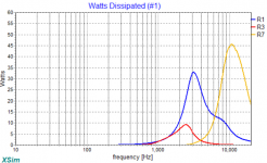
I played with it a bit and it has marginal impact to the power dissipation and impedance, but large affect on the frequency response
Changing that value is like adding the resistor in the second circuit. It damps the resonance. As it was in the first circuit, the 10u and 0m1 may have been a little hot, and by the way also encouraged the larger dissipation of the resistor.
However you need to know that Xsim is giving you a theoretical 100W at each frequency. In real music you're not going to see that at higher frequencies.
Some of the questions you have asked want you to turn on phase. Click on each driver and ask Xsim to derive phase for the factory data, then select phase for each on the chart (using the menus at the top).
Out of all the variations that measuring gives compared to doing it this way, the first thing you'll want to deal with is that your baffle will focus the higher frequencies more than the lower ones. At some point in the hundreds of Hz you may want the response to drop by a few dB or more.
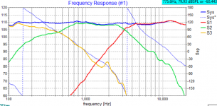
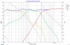
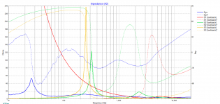
OK. Here are the Frequency response and impedance curves with phase (for the 1st crossover).
I'll do a little googling to figure out how to interpret good v. bad phase alignment
I'll do a little googling to figure out how to interpret good v. bad phase alignment
Attachments

Yes, the SLS12 is 8 ohm.
I don't have the dimensions of the driver layout at the moment. The current box, which I'll likely replace, has the tweeter and mid on a narrow baffle (approx. 8" wide) at the top, and the SLS12 on a wider baffler (approx. 20" wide) below.
I don't have the dimensions of the driver layout at the moment. The current box, which I'll likely replace, has the tweeter and mid on a narrow baffle (approx. 8" wide) at the top, and the SLS12 on a wider baffler (approx. 20" wide) below.
For now, you should get them to line up with each other. Telling just how good that is, is some next level work so it can wait for another day.I'll do a little googling to figure out how to interpret good v. bad phase alignment
The lower cross looks OK. Notice the green upper midrange lowpass strays from the red tweeter phase plot above around 3kHz, going on a different slope. You can bring these closer by increasing the slope of the mid by adjusting L3, R3, C6 on your original schematic, and possibly adjusting the tweeter as well.
You might get some ideas from the PSB Stratus Gold which has an XO that is very
similar to what you have. The woofer impedance is 4 ohms in the PSB so you'd have to
scale up the XO to match your 8 ohm.
The mid to woofer XO is much lower in the PSB.
PSB Stratus gold X-over help
similar to what you have. The woofer impedance is 4 ohms in the PSB so you'd have to
scale up the XO to match your 8 ohm.
The mid to woofer XO is much lower in the PSB.
PSB Stratus gold X-over help
I took some of the recommendations and made a few adjustments.
1. I made a few adjustments to achieve 3dB fall from 300 Hz to 2kHz for general baffle step compensation, then tried to flatten things out above 2kHz.
2. Shorted out (removed) R3 to bring the tweeter and mid into closer phase alignment. They're now within about 15 degrees at the XO point and within about 30 degrees until the mid falls off by 10dB below the tweeter. I think this is pretty good alignment, but would be curious to hear of there is a rule of thumb...
Attachments
-
 Crossover with Bafflestep tilt and phase alignment.png84.8 KB · Views: 134
 -
 Freq response with Bafflestep tilt and phase alignment.png284 KB · Views: 123
 -
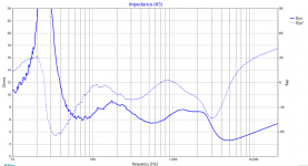 Impedance with Bafflestep tilt and phase alignment.png152.5 KB · Views: 113
 -
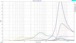 Power diss with Bafflestep tilt and phase alignment.png299.3 KB · Views: 126
Lining up phase either side of the crossover is the rule of thumb. 15-30 degrees separation isn't bad. Usually you try to get the slopes to run similarly.
I see your impedance gets lower around 4-5kHz, it isn't too bad. There is also a small response peak there and the whole tweeter could also stand to come down another smidgen in my humble opinion. If you want to play with resistances see that what you do achieves all these things at the same time.
I see your impedance gets lower around 4-5kHz, it isn't too bad. There is also a small response peak there and the whole tweeter could also stand to come down another smidgen in my humble opinion. If you want to play with resistances see that what you do achieves all these things at the same time.
Thanks Allen. I’ll play with the tweeter a little more to bring it down a touch and flatten that peak.
Do you think there is value in designing this crossover without in-box and on-baffle driver measurements? When measuring loudspeakers, do people find large variance from manufacturers response or impedance curves?
In-box measurement is mandatory, I’d say. While with a classic 2-way design and some rules of thumb you could get pretty close to a decent response, with a 3-way design you are in another ballpark. Mainly because the crossover between bass and mid combined with the baffle step can turn out pretty awkward when you are out there without the confirmation of measurements. Essentially, you are binning the advantage of a good 3-way design without measuring acoustic response.
- Home
- Loudspeakers
- Multi-Way
- 3 way crossover design help - 27 TDFC, MCA15RCY and SLS12